I finally was able to find an IBM PS/2 8540SX in a good esthetic shape with no plastic issue and all the very specific IBM screw on the back. The 8540 was one of the last (with the 8535) to be equipped with ISA bus and not the proprietary Micro Channel bus MCA. The is why, it is been highly chased by retro hunter.
In this case, this IBM was sold as not working and as it arrived the initial testing was not showing any sign of life.
The demand on this kind of computer is extremely high and almost with no offer at all, so when you see one appearing on the market one does not hesitate too long. The seller, was king enough to make the packaging strong to avoid any damages, especially on the plastic corners.
I was betting on the non starting root cause to be a faulty PSU and I was right. I soon as I replaced the PSU with a working one, it start straight to boot with the regular IBM PS/2 errors CMOS (161, 163).
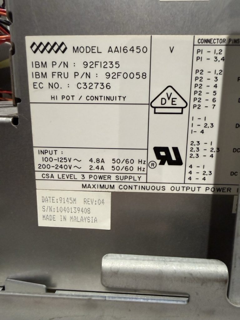
The 8540 PSU is the same as the 8557 and its part number is 92F0058

The PSU sticker, AASTEC is marked inside the PSU model is AAI6450
Finding a replacement PSU especially in Europe is quite impossible mission, and the only options are to repair it yourself, find someone to do it for you and buy a new one. I decided to try to repair it myself with limited knowledge on PSU repair process. As always, to solve issues the best way is to read, learn, as for support and questions. This is what I did.
I found very interesting YouTube video on PSU ATX repair.
With this video and other video from Learn Electronic Repair, I started understanding the big picture of how PSU are working,
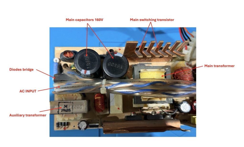
When you start putting your hand into a PSU, you have to understand that there is high voltage in the primary circuit (the circuit with the 2 big capacitor).
<!> You need to be extra careful and understand and know what you are doing.
Step 1: if you have plugged in the PSU on AC power, you should wait at least 30 min before operating from the Inside of the PSU, then measure the voltage at the diode bridge and discharge the main circuit with a 5K,5W resistance.
Step 2: on the other side of the PSU to check the fuse, as it can be burnt (but in that case replacing the fuse will not solve the root cause of the issue).
Using a multimeter in resistance continuity testing …
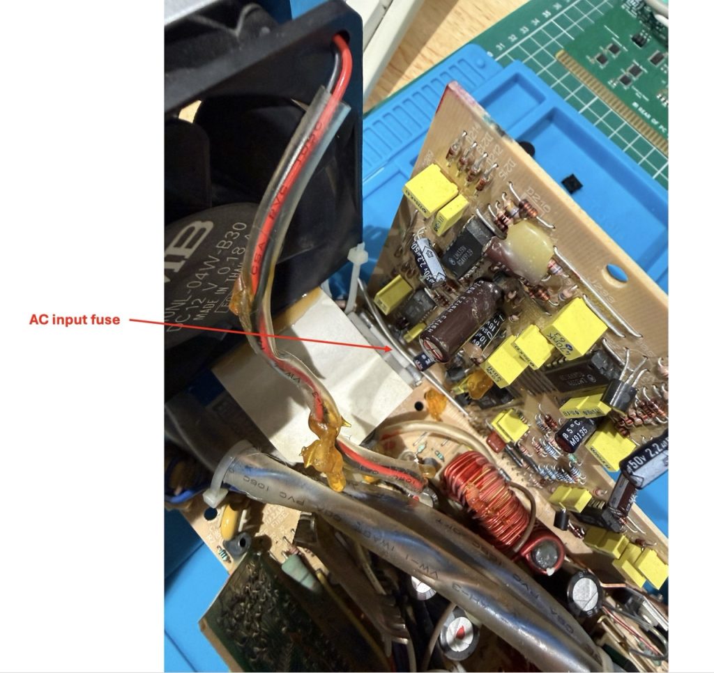
In my case the fuse was OK…
Step 3: visual check of the components for trace of burn, leakage, any defect. and in my case everything was OK.
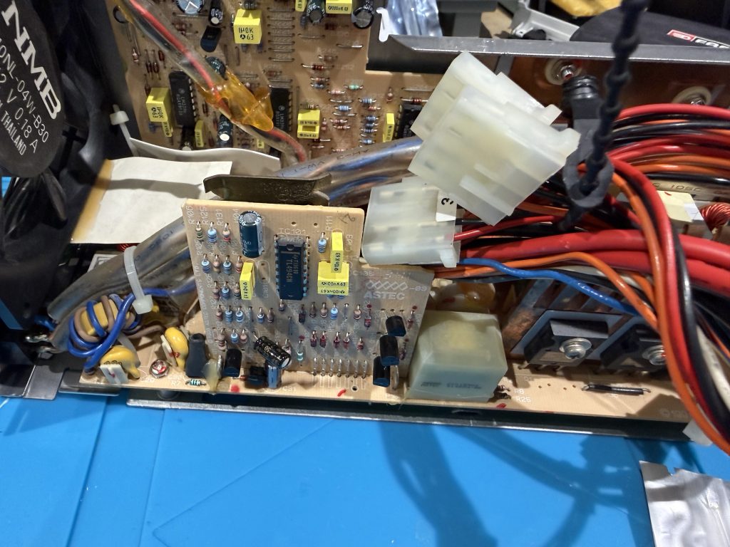
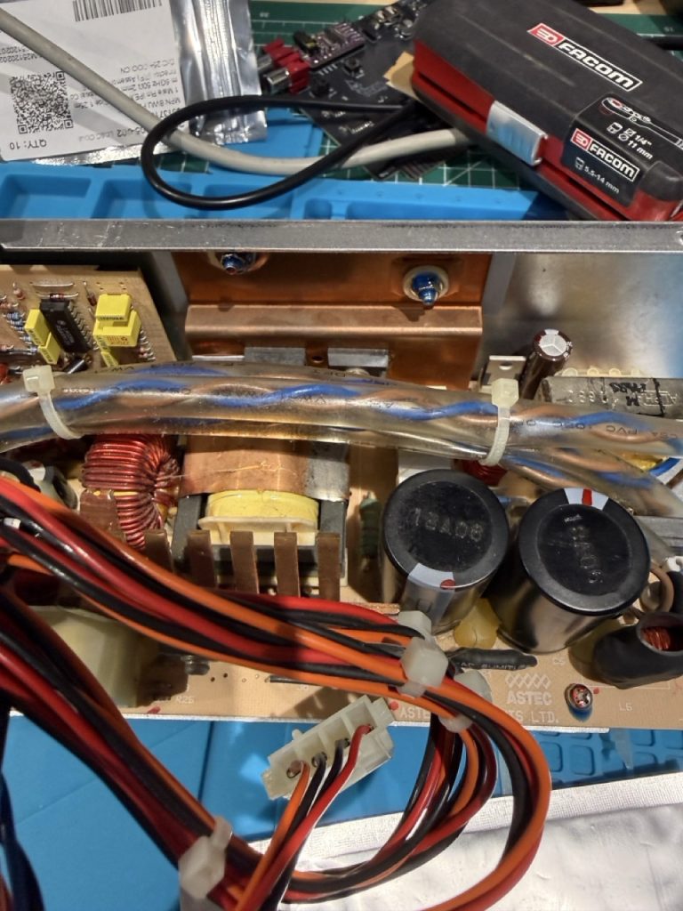
This PSU is made of 3 PCBs:
- PCB 1: The main board card with the primary circuit,
- PCB 2:The Trigger card, with the trigger on the P2 Connector,
- PCB 3: The PWM card that drives the main transistor on the primary circuit

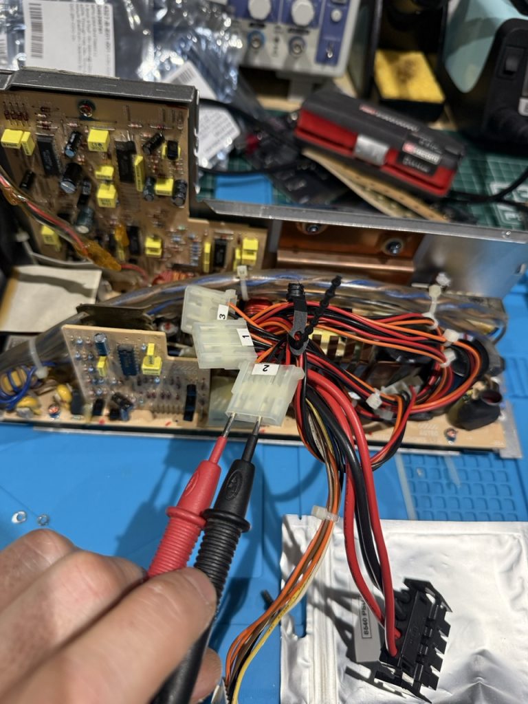
Motherboard connector

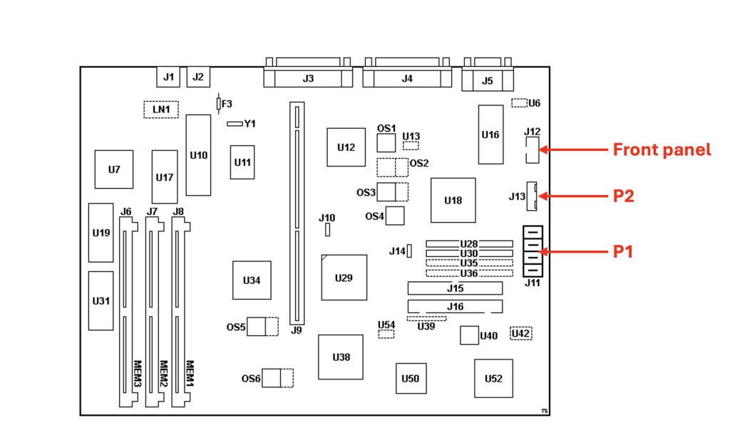

P2 Connector pinout

To manually start the PSU (without the motherboard), you have to short Pin 4 and Pin 6 (and to keep it shorted).
| Pin | Signal | V DC Min | V DC Max |
| 1 | +12V | +9V | +15V |
| 2 | +12V | +9V | +15V |
| 3 | Power Good | ||
| 4 | On/Off Switch | ||
| 5 | -12V | -9V | -15V |
| 6 | GND | ||
| 7 | -5V | -4.8V | -5.25V |
source: http://ps-2.kev009.com/basil.holloway/boo-to-pdf/S84F_7767_01.pdf
Step 4 (optional): Using the thermal camera check any high temperature on the 3 PCBs to detect any shorts that would generate an extra heat.
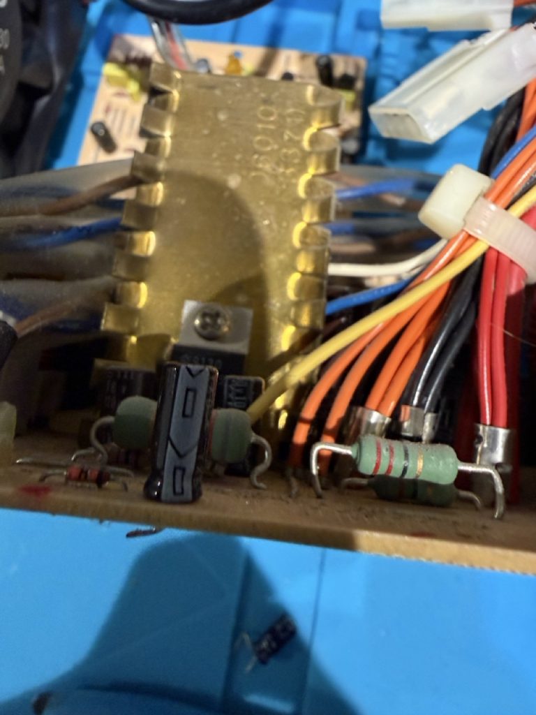
Please note on this PCB there is a thermistor in the main circuit. A thermistor is a temperature‑sensitive resistor, NTC thermistor: resistance decreases as temperature rises (common in temperature sensors and PSU inrush limiters). The purpose is to protect the capacitor when the AC flow starts in the circuit and to avoid shock. We should see this terminator using the thermal camera.
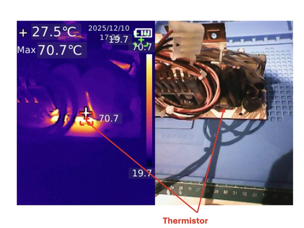
Except this thermistor, the temperature spectrum on the 3 PCB seems to be ok (even after shorting P2 pin 4 and 6 see before).

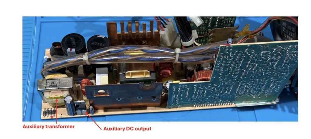
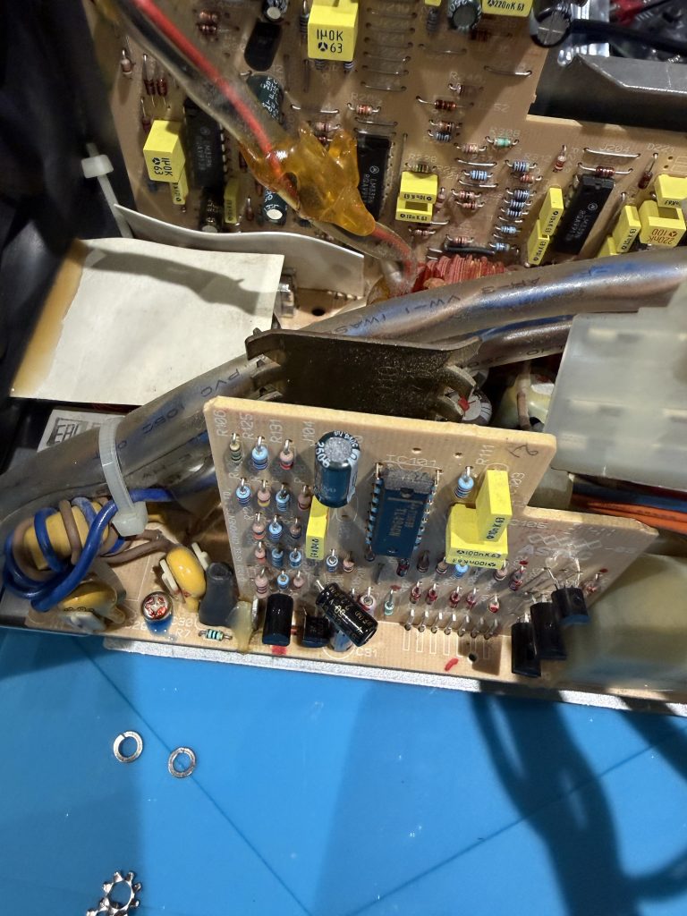
Step 5: deeper investigation and the auxiliary circuit and the trigger card.
Reading and watching video, the PWM board should be triggered by the trigger card. This step is to further investigate CARD 2 and CARD 3.
Keeping in mind that we are working with High voltage, I tried to understand the root cause of the issue.
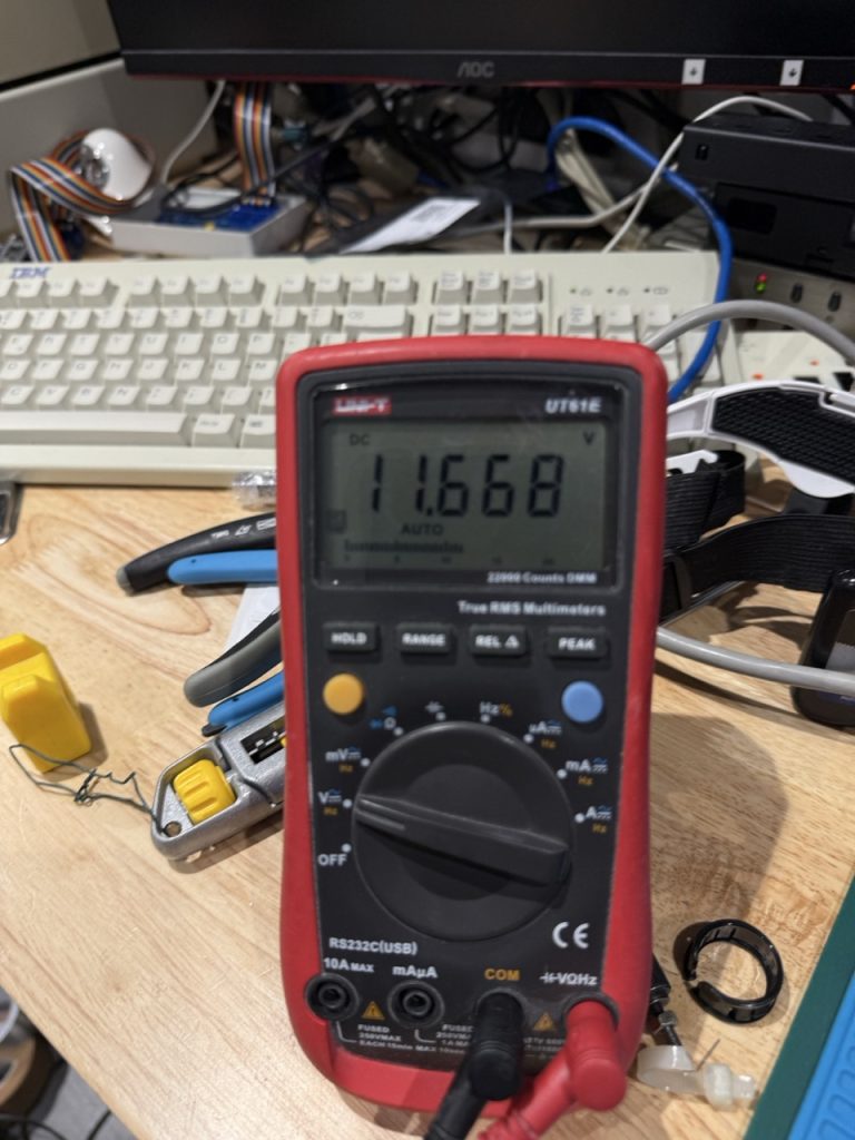
The first check was checking the auxiliary output marked above, and it gave me something around 11.6V which is not too bad.
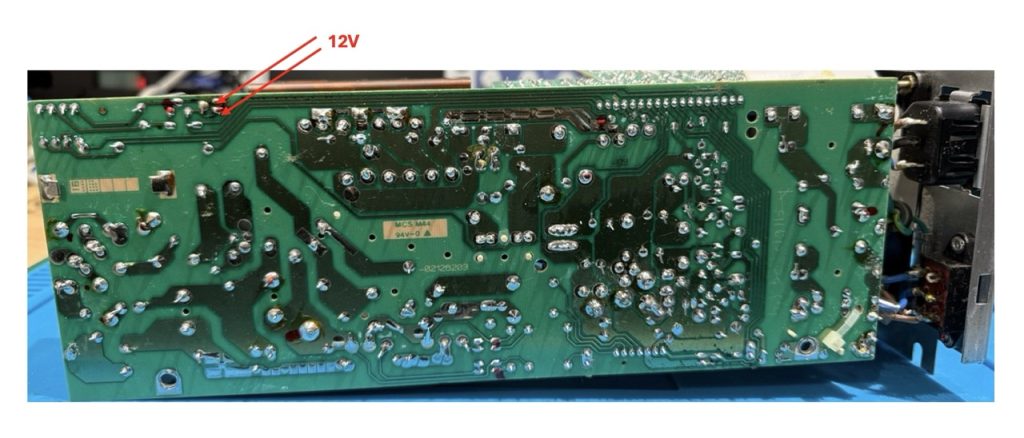
Then I wanted to check to PWM voltage rail and nothing was out to the PWM chip. When shorting ground on Connecter P2 pin6 & pin4 I should get some voltage on the TL494 (Card 3), but nothing. It means that the CARD 3 (PWM is not receiving any order from the trigger).
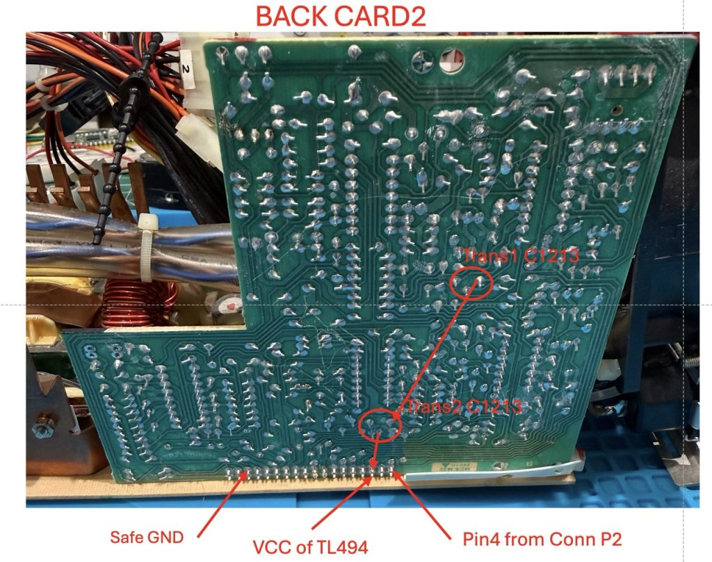
On card 3, we should have 12V on the TL494CN, when we simulate the frontend button to be pushed (connector P2).

At this stage, my guess was that one of the CARD 2 driving transistor was dead (and I was wrong).
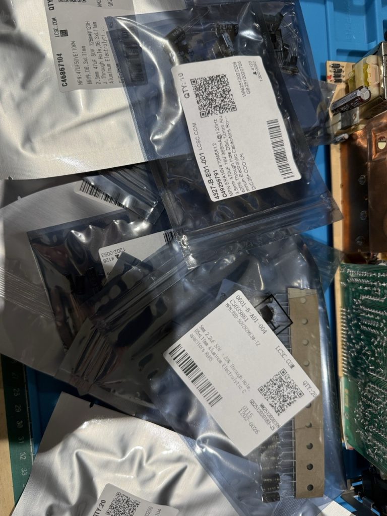
I ordered a few components on LCSC, to be able to do a full recap (when you tests, you take the time to replace…).
One important thing, is when you replace caps in PSU, low ESR is required to avoid any switching issues.
I put below a complete BOM of my order, but mainly caps, transistor and two type of IC (just in case).
But wait this board is a 35 years old PSU board, finding exact replacement for transistor was not possible. Here is after my search with the transistor alternatives I found.
| Old Reference | Alternative |
| 2SC1210 | 2SC1383-R |
| 2BS561 | 2SB562 |
| 2SC2120 | 2SC2129 |
| 2SC1213 | KSC2383OTA |
I received everything in less than 10 days
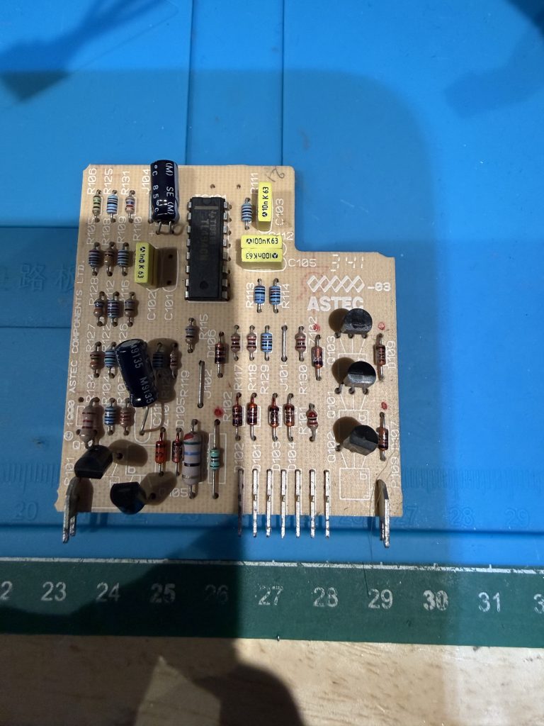
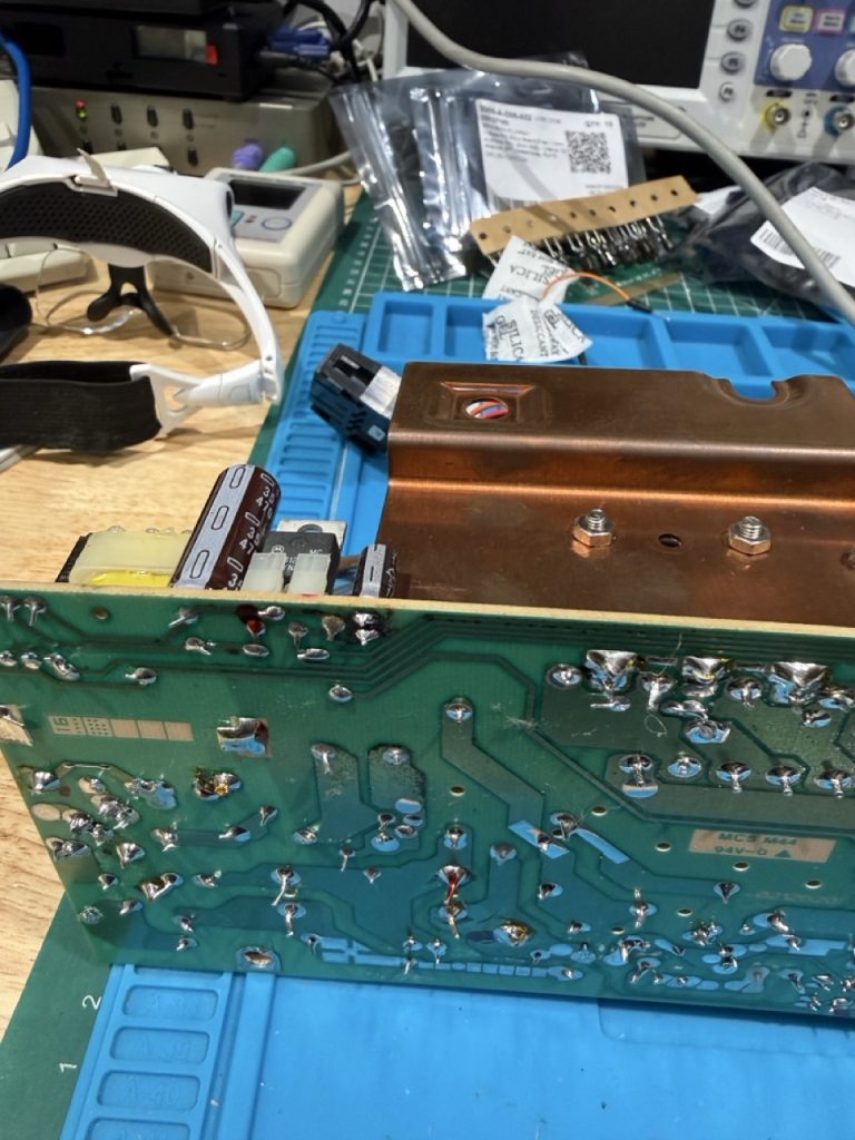
The next step was to desolder, the card2 from the card1, you need to be extra careful when push on/off the card2 because the solder mask is very fragile and you should cause break trace.
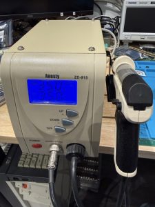
I use this machine to properly desolder everything
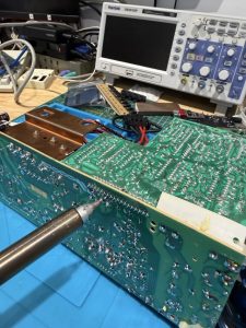
Without any issue I was able to remove the CARD 2 (Trigger card)
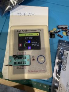
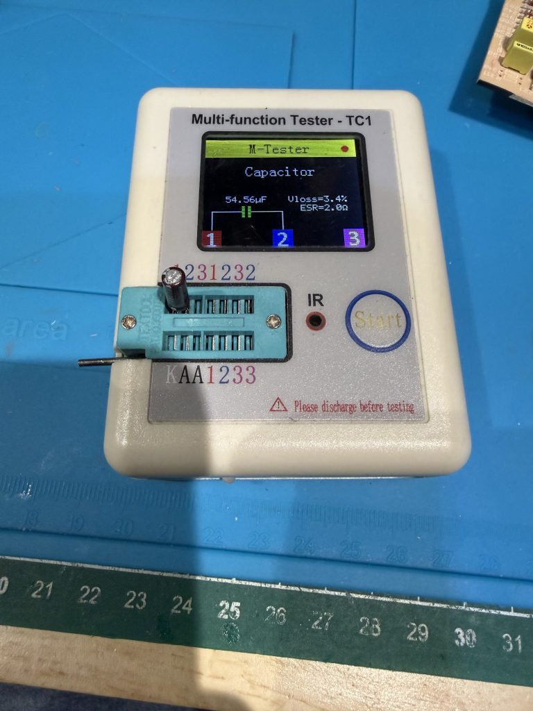
I did a full transistor and caps test, and change, without detecting any issues.
Checking everything with a proper tester:
After reinstalling the CARD 2 and desoldering and checking every solder, still no sign of life (a sign of life would have been my FAN start to blow something). My initial assumption was wrong.
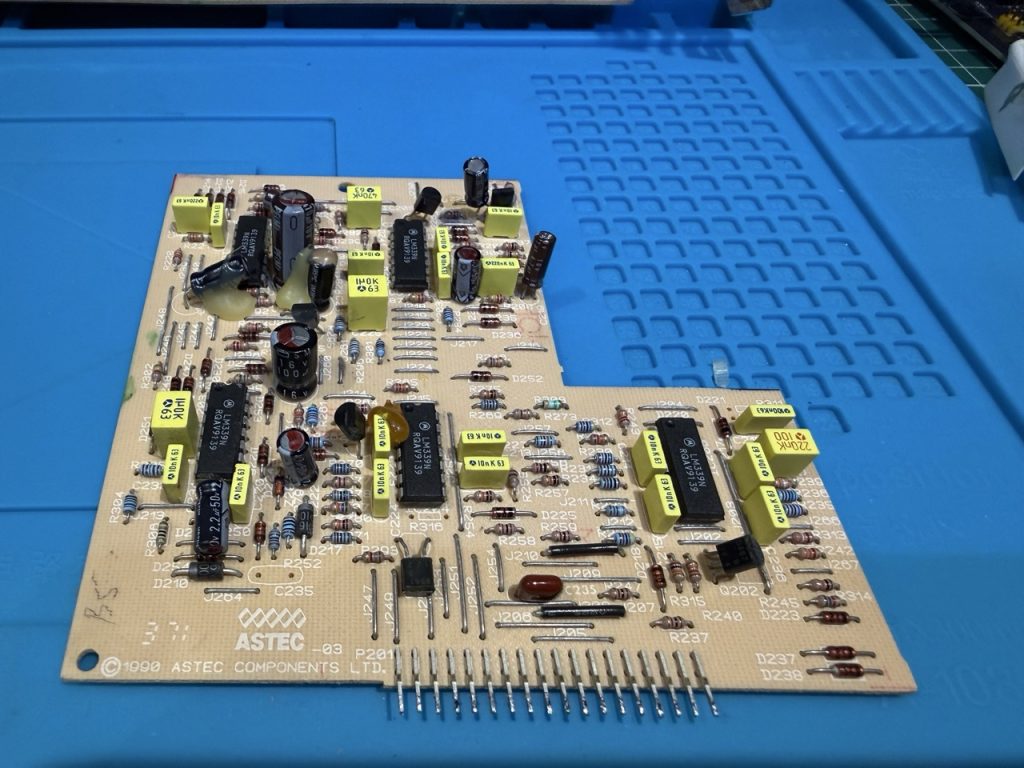
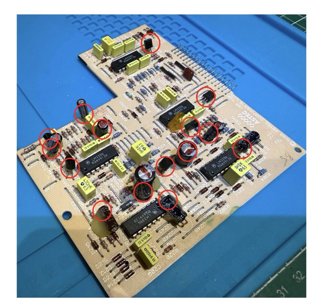
Then I decided to do the same with CARD 3 (complete transistor and caps test and change
In red circle, the test and change I made:

Before putting back the CARD3 in CARD1, I also decided to replace the 2 CARD1 caps (10uF 50V)
and the last one on CARD 1 next to the auxiliary transformer (10uF 50V)
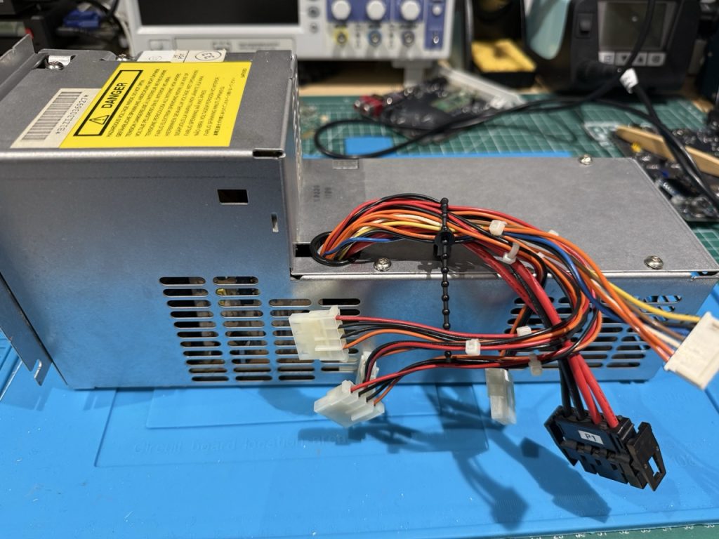
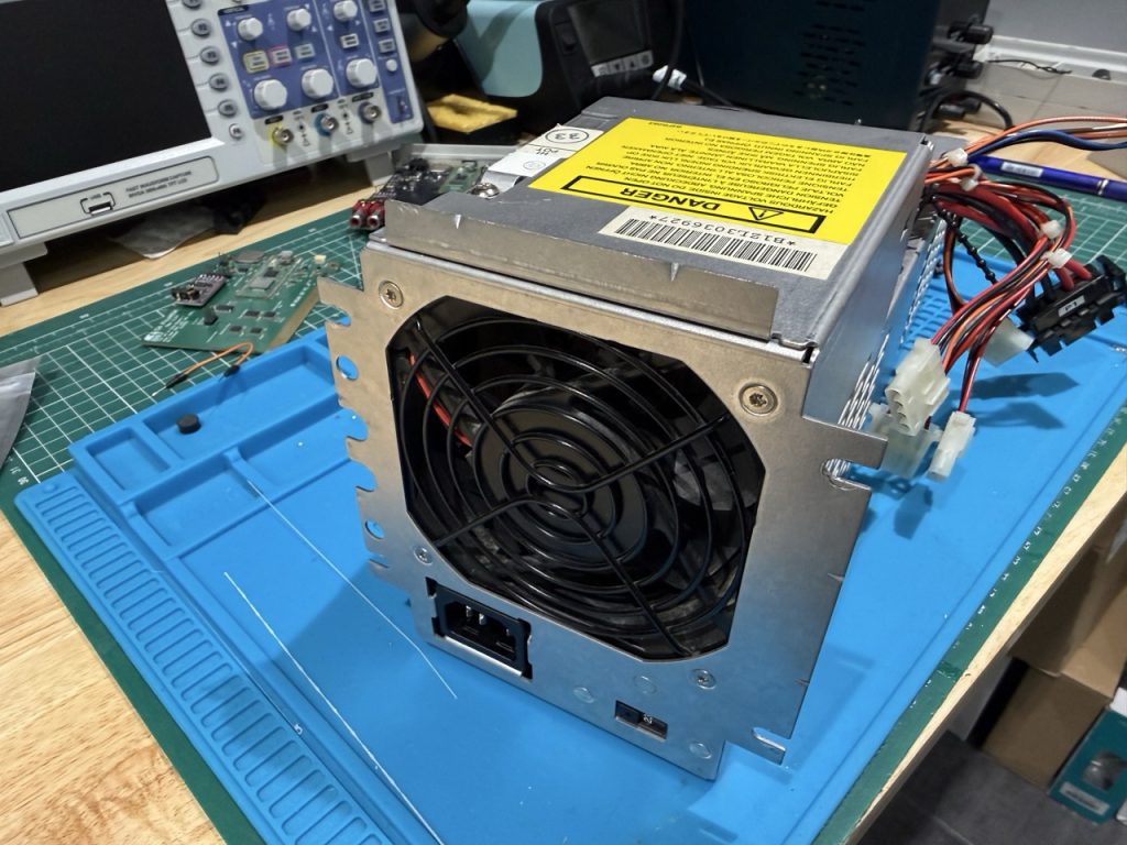
Putting everything back together:
At the stage, I was quite sure nothing would work, but the PSU did start and fresh air was blowing out of the FAN, VICTORY. The real question you would ask is why, because I test everything with tester and so on. Maybe a caps issue of bad cracking solder… who knows. but it is working
Checking the DC output rails:
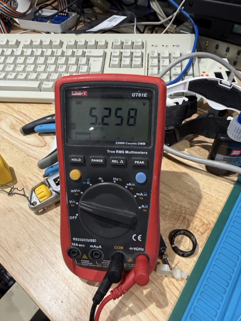

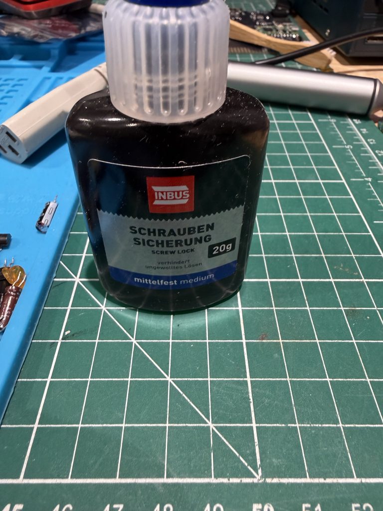
Not too bad after all, now it is time to put back the 3 PCB in the case, but before that I applied some screw lock on each of the 5 inside screw
I always use a small plastic bag to gather all the screw, and be organized to make sure I will not loose anything.

I do not know, if it will last another 30 years but my IBM 8540 has a working PSU.
Bill of Materials:
| Component | Description | Qty | LCSC # |
| 2SB562 C | 625mW 20V 1A PNP TO-92L Single Bipolar Transistors RoHS | 10 | C2688975 |
| 2SC1383-R | 25V 1W 1A NPN TO-92LM Single Bipolar Transistors RoHS | 10 | C358545 |
| 2SC2120 | 10 | C50229612 | |
| KSC2383OTA | 900mW 160V 1A NPN TO-92-3 Single Bipolar Transistors RoHS | 10 | C900961 |
| CAP 4.7UF 50V | 2mm 4.7uF 50V 2Ω ±20% 58mA@100KHz Through Hole,D5xL11mm Aluminum Electrolytic Capacitors RoHS | 10 | C46867052 |
| CAP ALUM 470uF 16V | 3.5mm 470uF 16V 366mA@120Hz ±20% Through Hole,D8xL12mm Aluminum Electrolytic Capacitors RoHS | 10 | C49256791 |
| CAP ALUM 10uF 50V | 2.5mm 10uF 50V 1.5Ω@100kHz ±20% 100mA@100kHz Through Hole,D5xL11mm Aluminum Electrolytic Capacitors RoHS | 10 | C3002459 |
| CAP ALUM 100uF ±20% 50V TH | 3.5mm 100uF 50V 170mΩ 550mA@100KHz ±20% Through Hole,D8xL12mm Aluminum Electrolytic Capacitors RoHS | 10 | C46867072 |
| CAP ALUM 2.2uF 50V | 5mm 2.2uF 50V ±20% Through Hole,D5xL11mm Aluminum Electrolytic Capacitors RoHS | 10 | C3039861 |
| TL494CN | TL494 Pulse-Width-Modulation Control Circuits | 2 | C5214 |
| LM339N | QUAD DIFFERENTIAL COMPARATORS | 4 | C725324 |
Thanks for reading, and I hope it will help other.
Vincent
Hi,
Thanks for posting this info – I’m going to add a link to it on Ardent Tool.
Could you please send me a photo of the PSU sticker? It looks like your PSU might be an AcBel API-9219 Rev. D.
I have a Rev. F, and it’s completely different internally. I’m planning to put together a tutorial on these PSUs, since two out of the three I recently picked up are dead.
Cheers,
Tom
Hello Thomas,
I will post on the article a photo of the sticker of the PSU, I remember that it is an AASTEC
Vincent