As I continue my journey building stuff based on Raspberry CPU, for one project I need to build a custom RP2350 board and to onboard on the PCB a WiFi Module.
Here is the source of the project on GitHub https://github.com/vibr77/ESP32C3_RP2350_WiFi
One could argue that using the recent release of the RM2 (existing on PICOW & PICO2W) would be the easiest solution. This is true, and the software integration (the driver) is also very mature and delivers very good performance.
The alternative approach is to consider module that would bring WiFi and Bluetooth supports. Many solutions on the market such as ATWINC1500 or the family of ESP32 products.
The key criterias for my projects are:
- Form factor,
- PCB integration capacity
- Performance,
- Maturity & openness,
- Cost
For all these reasons, I have selected the ESP32C3-WROOM-02-N4 chip from expressif
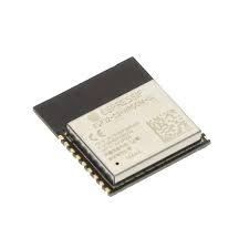
On-board PCB antenna or external antenna connector
- 2.4 GHz Wi-Fi (802.11b/g/n) and Bluetooth® 5 module
- Built around ESP32-C3 series of SoCs, RISC-V single-core microprocessor
- Flash up to 16 MB
- 15 GPIOs
This module is available widely and also proposed by many PCBA manufacturers such as JLCPCB and PCBWAY. And the average price for qty 10+ is approximately 2.5$ (quite cheap).
It bring everything need including the crystal, the flash, … ready to be integrated.
The form factor is also very small.
This module matches the following criteria:
- Form factor,
- PCB integration capacity
- Cost
From a maturity and performance hardware standpoint, this family of component is widely used in IOT and many benchmarks are available and are showing on the paper good results.
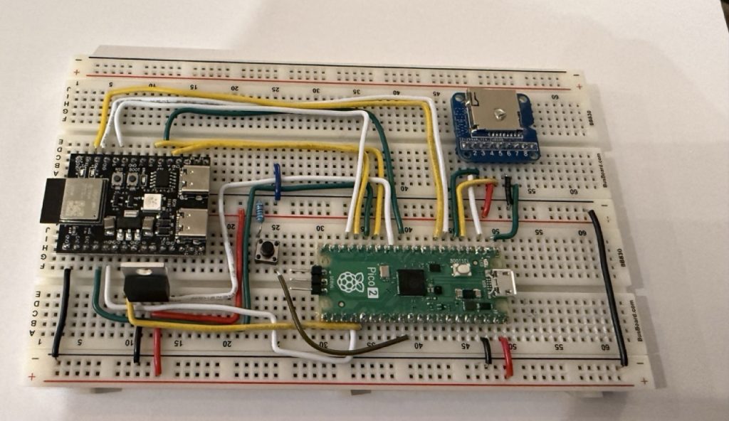
Experimentation breadboard
I use the following breadboard to test the integration of the RP2350A (Pico2 and the ESP32C3)
I use the following parts:
- Raspberry PICO2
- ESP32C3-Mini Board
- LMP1117T-3.3 IMPORTANT because the Pico2 is not able to deliver enough current during the Connect Phase
- PushButton Switch (Reset Circuit)
Software integration
The main question is the Software integration with the Raspberry Pico CPU family and to be able to reach the performance of the very RM2.
After search the web, I found the 2 GitHub repositories
ESP-Hosted Copying the readme:
ESP-Hosted is an open-source solution that enables Espressif SoCs/modules (like ESP32) to act as wireless communication co-processors for external host systems.
It allows host devices (Linux-based systems or microcontrollers, MCUs) to add Wi-Fi and Bluetooth/BLE capabilities via standard interfaces like SPI, SDIO, or UART.
ESP-AT Espressif SoCs serve as add-on modules, easily integrating wireless connectivity into existing products. To reduce development costs, Espressif offers a set of AT commands (select your target chip from the dropdown menu in the top left corner) that enable users to interface with Espressif products.
Conclusion
Within the list of the 3 ESP-HOSTED firmware (NG,FG,MCU) and the AT firmware, After hours of testing, playing with the different versions of the firmware, I came to the following conclusions:
- out of the box Pico integration does not exists,
- MCU is the best suit firmware solution to integrating with RP2350/RP2040
- A lot of work ahead to have it work and even more work to tune this up
The AT firmware:
Of course, I took the shortcut by testing the ESP-AT firmware. It is true that the integration is straightforward based on UART communication. the schema is very simple with only 2 GPIOs (UART TX,UART RX) to have the dialog between the PICO and the ESP32.
After flashing the ESP32C2 with the last AT firmware version, using either UART0 or UART1 on the PICO, the fun starts quite quickly
AT Command on UART:
### Basic Commands
```
AT                      - Test AT startup
AT+RST                  - Restart module
AT+GMR                  - Check version info
```

### WiFi Station Commands
```
AT+CWMODE=1             - Set WiFi mode to Station
AT+CWLAP                - List available APs
AT+CWJAP="SSID","PWD"  - Connect to AP
AT+CWQAP                - Disconnect from AP
AT+CIPSTA?              - Query Station IP address
```

### WiFi AP Commands
```
AT+CWMODE=2             - Set WiFi mode to AP
AT+CWSAP="SSID","PWD",5,3  - Configure AP (ch=5, enc=WPA2_PSK)
```

### TCP/IP Commands
```
AT+CIPSTATUS            - Get connection status
AT+CIPSTART="TCP","192.168.1.1",8080  - Start TCP connection
AT+CIPSEND=10           - Send 10 bytes of data
AT+CIPCLOSE             - Close connection
```
Pin Configuration
RP2040/RP2350 side
- UART pins for AT communication:
- **TX** (RP2040 GPIO36) → **RX** (ESP32 GPIO6)
- **RX** (RP2040 GPIO37) ← **TX** (ESP32 GPIO7)
ESP32-C3 AT Firmware Side
- Port: UART1
- TX: GPIO7 (connects to RP2040 GPIO37)
- RX: GPIO6 (connects to RP2040 GPIO36)
- CTS: GPIO5 (not connected, hardware flow control disabled)
- RTS: GPIO4 (not connected, hardware flow control disabled)
- Baudrate: 115200 (default)
The following code can be used to test the ESP with AT Firmware setup and the Pico:
void handle_at_test(void) {
    printf("\n=== AT Command Test ===\n");
    printf("Testing basic AT communication...\n\n");

    // Clear any pending data first
    uint8_t dummy[256];
    while (esp32_uart_read(dummy, sizeof(dummy)) > 0) {
        sleep_ms(10);
    }

    printf("Sending: AT\\r\\n");
    size_t sent = esp32_uart_write_string("AT\r\n");
    printf("Sent %zu bytes\n", sent);

    // Wait for response with multiple attempts
    printf("Waiting for response...\n");
    uint8_t rx_buf[256];
    int total_len = 0;

    for (int attempt = 0; attempt < 20; attempt++) {
        sleep_ms(50);
        int rx_len = esp32_uart_read(rx_buf + total_len, sizeof(rx_buf) - total_len - 1);
        if (rx_len > 0) {
            printf("  [%d] Received %d bytes\n", attempt, rx_len);
            total_len += rx_len;
        }

        // Check if we got OK
        if (total_len > 0) {
            rx_buf[total_len] = '\0';
            if (strstr((char*)rx_buf, "OK") != NULL) {
                break;
            }
        }
    }

    if (total_len > 0) {
        rx_buf[total_len] = '\0';
        printf("\n✓ Response (%d bytes):\n%s\n", total_len, rx_buf);

        // Print hex dump for debugging
        printf("\nHex dump: ");
        for (int i = 0; i < total_len && i < 32; i++) {
            printf("%02X ", rx_buf[i]);
        }
        printf("\n");
    } else {
        printf("\n✗ No response received\n");
        printf("\nTroubleshooting:\n");
        printf("  1. Check UART wiring (TX↔RX crossed)\n");
        printf("  2. Verify ESP32 is running AT firmware\n");
        printf("  3. Use Option 17 to monitor ESP32 UART output\n");
        printf("  4. Try resetting ESP32 (Option 1)\n");
    }
}
All the AT functions are available on the project GitHub repository, I have also made a small LWIP integration to be able to use a TCP/IP stack,
Everything is working smoothly and very fast, however the main drawback of this solution is that it relies on UART, and UART is a serial communication without a clock signal. Even with changing the baud rate to 921 600 bps (the extreme limit for reliability) you do not get strong performance at all. This is mainly due to the UART speed but also to the overhead firmware inside serial communication to transport packet.
I manage to do some testing with a remote iperf server in the same subnet and I have collected the following results:
void handle_at_test(void) {
    printf("\n=== AT Command Test ===\n");
    printf("Testing basic AT communication...\n\n");

    // Clear any pending data first
    uint8_t dummy[256];
    while (esp32_uart_read(dummy, sizeof(dummy)) > 0) {
        sleep_ms(10);
    }

    printf("Sending: AT\\r\\n");
    size_t sent = esp32_uart_write_string("AT\r\n");
    printf("Sent %zu bytes\n", sent);

    // Wait for response with multiple attempts
    printf("Waiting for response...\n");
    uint8_t rx_buf[256];
    int total_len = 0;

    for (int attempt = 0; attempt < 20; attempt++) {
        sleep_ms(50);
        int rx_len = esp32_uart_read(rx_buf + total_len, sizeof(rx_buf) - total_len - 1);
        if (rx_len > 0) {
            printf("  [%d] Received %d bytes\n", attempt, rx_len);
            total_len += rx_len;
        }

        // Check if we got OK
        if (total_len > 0) {
            rx_buf[total_len] = '\0';
            if (strstr((char*)rx_buf, "OK") != NULL) {
                break;
            }
        }
    }

    if (total_len > 0) {
        rx_buf[total_len] = '\0';
        printf("\n✓ Response (%d bytes):\n%s\n", total_len, rx_buf);

        // Print hex dump for debugging
        printf("\nHex dump: ");
        for (int i = 0; i < total_len && i < 32; i++) {
            printf("%02X ", rx_buf[i]);
        }
        printf("\n");
    } else {
        printf("\n✗ No response received\n");
        printf("\nTroubleshooting:\n");
        printf("  1. Check UART wiring (TX↔RX crossed)\n");
        printf("  2. Verify ESP32 is running AT firmware\n");
        printf("  3. Use Option 17 to monitor ESP32 UART output\n");
        printf("  4. Try resetting ESP32 (Option 1)\n");
    }
}
At 115200 baud (default):
- Duration: 10.09 seconds
- Total sent: 98,310 bytes (0.09 MB)
- Chunks sent: 97
- Send errors: 0
- Throughput: 9.52 KB/s (77.98 Kbps / 0.078 Mbps)
- Theoretical max: ~11.5 KB/s
- Actual: **9.5 KB/s** (83% efficiency)
- AT command overhead: ~17%
✅ At 460800 baud (recommended):
- Duration: 10.00 seconds
- Total sent: 237,574 bytes (0.23 MB)
- Chunks sent: 233
- Send errors: 0
- Throughput: 23.20 KB/s (190.05 Kbps / 0.190 Mbps)
- Theoretical max: ~46 KB/s
- Actual: **20-23 KB/s** (43-50% efficiency)
- AT command overhead: ~50-57%
- 2.1-2.4x speed improvement over 115200 baud
- Performance varies based on network conditions and server responsiveness
At 921600 baud (ultra-high-speed)
- Duration: 10.02 seconds
- Total sent: 212,998 bytes (0.20 MB)
- Chunks sent: 209
- Send errors: 0
- Throughput: 20.77 KB/s (170.11 Kbps / 0.170 Mbps)
- Theoretical max: ~92 KB/s
I suspect some external factors limiting the results of the tests, but still the overall performance of the AT Firmware based on UART is low and suitable for small IoT projects (which is not my case).
To summarize the Experience of the AT firmware:
✅ Good:
- Easy to integrate,
- very few GPIO used,
- Software integration is straightforward,
❌ Bad:
- Performance are poor for non IoT project, when above 1MB throughput is required. the RM2 WiFi module using SPI can delivery 4-6 Mbps throuput.
I will keep my work on using the AT firmware for any small IoT project that does not require strong performance but straightforward integration.
The ESP-HOSTED-MCU firmware, the Cliff…
After spending a couple of hours on internet to find a clean integration of this firmware, I came to the conclusion that I will have to do it by myself… (maybe I miss a project that exists).
There are some exemples of integration using the ESP32 communicating with another ESP32 but not track record of using a RP2040 or RP2350 to with the ESP32-HOSTED-MCU…
I even tried to use a bit of AI with Claude Antropic, and every time the agent proposed to switch to the AT firmware to avoid the integration complexity… It is a signal that things will not be as easy as I thought.
The truth is that the existing documentation is very light and does go into details, and it is not easy to get the full picture.
My exploration:
The firmware relies either on SPI or SDIO, and I choose to use SPI integration. On top the SPI GPIO (MISO,MOSI,CLK,CS), 2 additional GPIOs are needed: Data Ready DR, and Handshake. A total of 6 GPIOs (compared to the 2 of the AT Firmware). If you want a full integration including firmware update 4 additional GPIOs are needed (BOOT, EN, UART TX, UART RX).
My project requires to be able to update the ESP32 firmware and I have done a 6+4 GPios integration.
GPIO Description:
- SPI MISO: classic Master Input, Slave Output , SPI RX
- SPI MOSI, classic Master Output, Slave Input, SPI TX
- SPI CLK, clock signal
- SPI CS, Active Low Chip Enable signal (it will play an important role in)
- Handshake: Active High, High when the ESP32 is ready to start a SPI transaction,
- Data Ready: Active High, High when data are to be transferred from the ESP32 to the RP2040/2350.
Global Process flow:
The RP2040/RP2350 is the Host Master, the slave is the ESP32.
- The Master to send Data to the slave: the Master asserts (active low) the CS GPIOs when the handshake signal is HIGH (active High) to signal that a new SPI transaction will happen. Then the master sends data via the SPI. The Master deassert the CS GPIOs to signal the end of the transaction. This last point is extremely important, otherwise it will disturb the ESP32 ISR.
The Slave to send data to the Master: the slave signal with the DATA READY GPIO that a new data chunk is ready. The Master starts the same dialog as the previous one, and then the slave dessert the DATA READY GPIO
The GPIO mapping used:
- SPI MOSI (Master Out): GPIO2
- SPI MISO (Slave Out): GPIO5
- SPI CS: GPIO10
- SPI CLK: GPIO6
- Handshake: GPIO3
- Data Ready: GPIO04
- BOOT: GPIO09
- EN: Reset Pin
Connection Table
| RP2350B | Function | Direction | ESP32-C3 |
| GPIO04 | SPI MISO | Input | GPIO05 |
| GPIO06 | SPI SCK | Output | GPIO06 |
| GPIO07 | SPI MOSI | Output | GPIO02 |
| GPIO08 | SPI CS | Output | GPIO10 |
| GPIO09 | Handshake | Input | GPIO03 |
| GPIO10 | Data Ready | Input | GPIO04 |
| GPIO40 | BOOT | Output | GPIO09 |
| GPIO39 | EN | Output | RESET |
| GND | Ground | GND | GND |
| GPIO04 | UART TX | Output | GPIO20 |
| GPIO05 | UART RX | Input | GPIO19 |
One very common mistake when doing prototyping is to forget to have a common ground between to active part dialoging via GPIO wire. In spent a few hours to understand this very obvious statement. The RP2350 and the ESP32 need to have a common ground do not forget it.
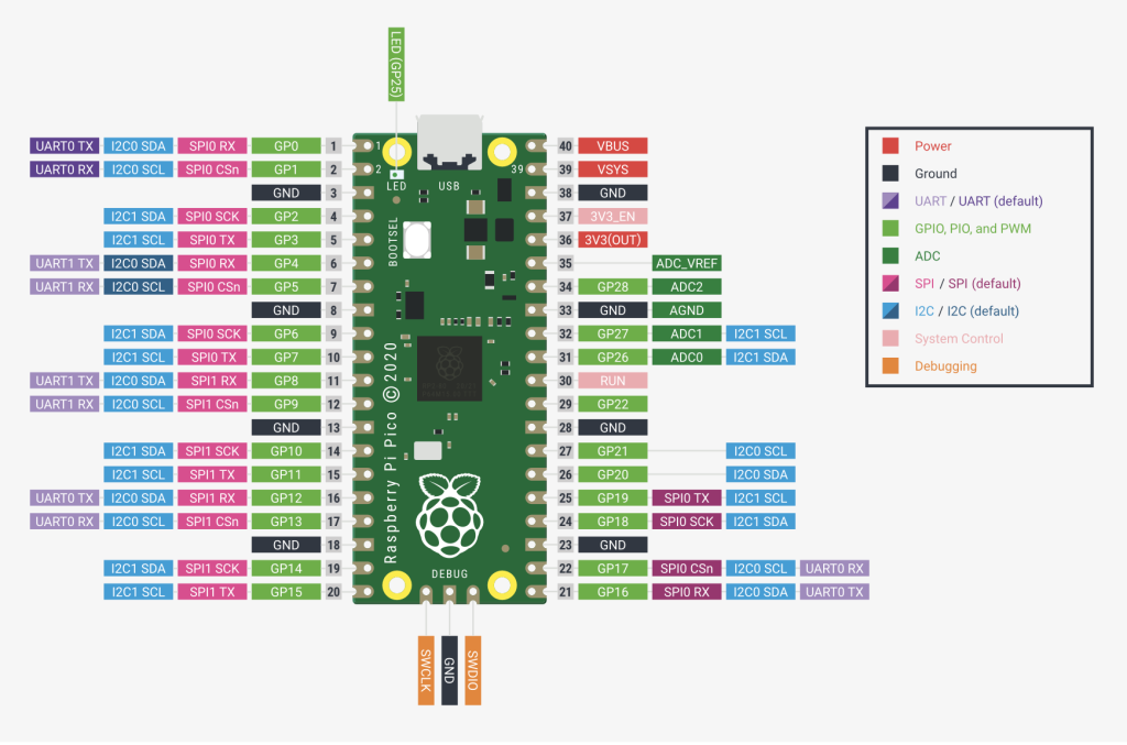
The pin setup on the Pico can be changed very easily, however one needs to follow the at least the available UART / SPI0 & SPI1 schemes. This is the same for the ESP32, for my need I changed the GPIO setup in the firmware sdkconfig file. You can check the proper ESP32 pin configuration during the boot upon the firmware using the UART terminal connexion with log level information.
Now lets start the software integration
Software integration
The project source code is available on GitHub here,
The following capabilities has been developed:
- SPI Communication
- WiFi Module Init
- WiFi Connexion / Disconnexion
- LWIP stack integration
- ESP32 Reset & Firmware update.
The project structure is the following:
```
Project Source
├── CMakeLists.txt               # Build configuration
├── README.md                    # Project Description
├── THROUGHPUT_TEST.md           # Network performance testing guide
├── NETWORK_ARCHITECTURE.md      # lwIP integration details
├── include/                     # Header files
│   ├── pin_config.h             # Gpio Pin definitions
│   ├── esp32_control.h          # ESP32 control functions
│   ├── esp32_spi.h              # SPI interface
│   ├── esp32_uart.h             # UART interface
│   ├── esp_hosted_mcu_control.h # ESP-Hosted-MCU protocol
│   ├── esp_hosted_mcu_rpc.h     # RPC implementation
│   ├── wifi_manager.h           # WiFi management
│   ├── lwip_netif.h             # lwIP network interface
│   ├── lwip_tcp_test.h          # TCP throughput testing
│   ├── lwipopts.h               # lwIP configuration
│   └── firmware_uploader.h      # Firmware upload
└── src/                         # Source files
    ├── main.c                   # Main application
    ├── esp32_control.c          # ESP32 control implementation
    ├── esp32_spi.c              # SPI implementation
    ├── esp32_uart.c             # UART implementation
    ├── esp_hosted_mcu_control.c # ESP-Hosted-MCU implementation
    ├── esp_hosted_mcu_rpc.c     # RPC implementation
    ├── wifi_manager.c           # WiFi implementation
    ├── lwip_netif.c             # lwIP bridge to ESP-Hosted
    ├── lwip_tcp_test.c          # TCP throughput test
    └── firmware_uploader.c      # Firmware upload implementation
```
The Typical End to End process flow from Boot to use of LWIP:
- Step 1: Setup the GPIO configuration for Data Ready and Handshake,
- Step 2: Init the SPI communication protocol,
- Step 3: Reset the ESP32,
- Step 4: Handshake with the ESP32,
- Step 5: Configure the WiFi,
- Step 6: Init the Wifi Module,
- Step 7: Connect Wifi,
- Step 8: Enable the LWIP Stack,
- Step 9: use Data.
Step 1: Setup the GPIO configuration
The function to configure the GPIO is located in esp32_control.h
void esp32_control_init(void);It will configure the following GPIO (Direction, level):
- BOOT (BOOT MODE)
- EN (RESET)
- HANDSHAKE
- DATA READY
The pin assignments are available in pin_config.h
Step 2: Init the SPI Communication Protocol
The function to init SPI is located in esp32_spi.c :
void esp32_spi_init(void);it uses the followings define in pin_config.h
#define ESP32_SPI_INSTANCE  spi1
#define ESP32_SPI_MISO      8               // RX   ESP32 GPIO05
#define ESP32_SPI_MOSI      11              // TX   ESP2  GPIO02
#define ESP32_SPI_SCK       10              // CLK  ESP32 GPIO06
#define ESP32_SPI_CS        9               // CS   ESP32 GPIO10
but also:
#define ESP32_SPI_BAUDRATE (25 * 1000 * 1000) /the SPI mode is 3, and after doing test on a breadboard, 25 Mhz for SPI clock frequency works perfectly, and using the clean pcb, one should be able to increase the speed to 40 MHz and thus the overall throughput of the solution
Step 3: Reset the ESP32
This step is of course not mandatory is you have already triggered a connexion to the ESP32.
The reset function is located in esp32_control.c:
void esp32_reset(void);It will simply toggle the EN pin for a few milliseconds to trigger a reset of the ESP32.
Step 4: Handshake with the ESP32
This is were the complexity starts, but it will be sorted out diligently;)
The ESP32 is sending 2 type of Information:
- Control packet,
- Data packet
Control packet are used to send event from the ESP32 to the PICO (Init, Configuration Success, Connect , Disconnect,…)
Data packet are regular TCP/IP data packets
Just right after the RESET, the ESP32 send a control packet called INIT and the Master (RP2350/RP2040) should capture it when Data Ready is HIGH and when Handshake is HIGH (both active High signal).
Both Control packet & Data packet processing is managed by a central function through 2 circular buffers.
The central function is driven by HANDSHAKE & DATA READY ISR located in esp32_control.c
static void data_ready_irq_handler(uint gpio, uint32_t events);This Interrupt function will monitor both EDGE RISE of HANDSHAKE & DATA READY.
Packet are process via the callback function defined during the INIT process located in esp32_control.c:
void esp32_set_packet_callback(void (*callback)(void));The callback is defined by:
esp32_set_packet_callback(&process_packets_immediate);The function process_packets_immediate defined is main.c
it will process by batch of 5 packets message queue to avoid the ISR blocking too long using the function defined in esp_hosted_mcu_control.c
esp_hosted_mcu_process_packets()It will manage the split of packet according to the type control / data
Here we are looking for INIT packet to be sent to the control packet queue.
control_packet_enqueue(&g_control_queue, &rx_header, rx_payload, len);The function located in esp_hosted_mcu_control.c is in charge of handshake execution:
bool esp_hosted_mcu_handshake(void);Step 5: Init the WiFi
The following sequence of code is needed to be done to init the WiFi
printf("Initializing WiFi...\n");
    if (!esp_hosted_rpc_wifi_init()) {
        printf("✗ WiFi init failed\n");
        return;
    }
    esp32_state=ESP32_STATE_WIFI_INIT;

    // Set WiFi mode to STA
    printf("Setting WiFi mode to STA...\n");
    if (!esp_hosted_rpc_set_wifi_mode(1)) {  // 1 = WIFI_MODE_STA
        printf("✗ Failed to set WiFi mode\n");
        return;
    }

    // Start WiFi
    printf("Starting WiFi...\n");
    if (!esp_hosted_rpc_wifi_start()) {
        printf("✗ WiFi start failed\n");
        return;
    }
Step 6: Configure the Wifi
printf("\nConfiguring WiFi credentials...\n");

    // WiFi should already be initialized and started by handle_mcu_test() at boot
    // Just configure credentials and connect

    rpc_wifi_config_t config;
    memset(&config, 0, sizeof(config));

    const char *ssid = "SSID";
    const char *password = "PASSWORD";

    strncpy(config.ssid, ssid, sizeof(config.ssid) - 1);
    strncpy(config.password, password, sizeof(config.password) - 1);

    // Update status: connecting
    wifi_status_set_connecting(config.ssid);

    printf("Setting WiFi config for '%s'...\n", config.ssid);
    if (!esp_hosted_rpc_set_wifi_config(&config)) {
        printf("✗ Failed to set WiFi config\n");
        return;
    }
    printf("✓ WiFi config set\n");

    // Brief delay for config processing
    sleep_ms(500);
Step 7 Connect to the WiFi
    printf("\nConnecting to '%s'...\n", config.ssid);
    if (esp_hosted_rpc_wifi_connect()) {
        // WiFi connect returns true if request succeeded, but doesn't guarantee connection
        // Wait for connection to complete with retries
        wifi_ap_record_t ap_info;
        bool connected = false;
        bool connection_failed = false;
        bool seen_connect_event = false;

        printf("Waiting for WiFi connection to complete");
        for (int attempt = 0; attempt < 30; attempt++) {  // 30 seconds timeout (1s per attempt)
            printf(".");
            fflush(stdout);
            sleep_ms(1000);  // Wait 1 second between attempts

            // Process any RPC events (like disconnect events indicating auth failure)
            // This will call esp32_event_handler() for any pending events
            esp_hosted_mcu_process_queued_control_packets();

            // Check WiFi state machine
            wifi_status_singleton_t* status = wifi_status_get();

            // Debug: show current state
            if (attempt == 0 || status->connection_state != WIFI_STATE_CONNECTING) {
                printf("[state=%d:%s]\n", status->connection_state,
                wifi_status_connection_state_str(status->connection_state));
                fflush(stdout);
            }

            // Track if we see a connect event
            if (status->connection_state == WIFI_STATE_CONNECTED) {
                seen_connect_event = true;
            }

            // Only treat disconnect as failure if:
            // 1. We've waited at least 3 seconds (allow handshake time)
            // 2. We either saw a connect event, or we're past second 5 with no connect
            if (status->connection_state == WIFI_STATE_DISCONNECTED &&
                (attempt >= 3 || (attempt >= 5 && !seen_connect_event))) {
                // Connection was explicitly rejected by ESP32
                printf("\n✗ WiFi connection failed with reason: %s\n",
                       wifi_status_disconnect_reason_str(status->disconnect_reason));
                connection_failed = true;
                break;
            }

            if (status->connection_state == WIFI_STATE_CONNECTED) {
                // Successfully connected - get AP info for display
                if (esp_hosted_rpc_wifi_sta_get_ap_info(&ap_info) && ap_info.ssid[0] != '\0') {
                    connected = true;
                    break;
                }
            }
        }
        printf("\n");

        if (connected) {
            // Connection verified - AP info has non-empty SSID matching our request
            printf("✓ Successfully connected to '%s'!\n", config.ssid);

            wifi_status_set_connected(
                (char*)ap_info.ssid,
                ap_info.bssid,
                ap_info.channel,
                ap_info.rssi,
                ap_info.authmode
            );

            // Get network config and update status
            rpc_dhcp_status_t dhcp_status;
            if (esp_hosted_rpc_get_dhcp_status(&dhcp_status) && dhcp_status.dhcp_up) {
                wifi_status_update_network(
                    dhcp_status.ip,
                    dhcp_status.gateway,
                    dhcp_status.netmask,
                    dhcp_status.dns_up ? dhcp_status.dns : NULL
                );
            }

            esp32_state=ESP32_STATE_WIFI_CONNECTED;
        } else if (connection_failed) {
            // Connection was explicitly rejected by ESP32 (disconnect event received)
            printf("✗ Connection rejected by ESP32\n");
            wifi_status_set_disconnected(WIFI_REASON_AUTH_FAIL);
        } else {
            // Connection timeout - stuck in CONNECTING state after 30 seconds
            // This usually indicates wrong password or network not responding
            printf("✗ Connection timeout after 30 seconds\n");
            printf("WiFi remains in CONNECTING state - possible causes:\n");
            printf("  - Incorrect SSID or password (most likely)\n");
            printf("  - AP out of range\n");
            printf("  - Network authentication issues\n");
            printf("  - ESP32 WiFi not responding\n");
            wifi_status_set_disconnected(WIFI_REASON_AUTH_FAIL);
        }
To be continued with the performance running and outcome in part 2