
After a few years to inactively searching for an IBM 5170 (the holy grail), I finally found an auction on a french domestic website. And luckily enough, I was proposed 2 monitors to come with it:
- IBM 5151 12’’ TTL Logic monochrome monitor
- IBM 5175 Professional Graphics Display (monitor for PGC card),
Of course, the 5170 was not booting with many defects:
- Hard-drive failure,
- Battery failure,
- …
Inside the 5170, a MDA (IBM Monochrome display adapter) card was found. The MDA card is working with the 5151 monitor.
No PGC card…
Both monitors were dusty, with spiderweb, dirty, as you can imagine with being stocked for the last 25 years… And I wanted to check if they were working.
The 5151 was surprisingly working fine with a bright and clear green on black image. The 5170 was nicely displaying the list of error due to all the defects.
I tried to power on the 5175 after plugin the power cord. There is a power switch in the front, and switch on has no effect, even the small green led was not showing any sign of life.
After less than 1 minute, I saw white smoke coming out of the top with a nasty smell, like if the monitor was having a fire inside.
I put the 5175 outside, waiting for the smoke to stop… I have seen this kind of thing happening with old Apple II PSU and Security Capacitor on the AC lines. A typical smell of roasted peppers and smoke predominates.
After reading some very good post on the internet, I decided to resurrect this 5175 and to have it working with my old dusted IBM PC 5170.
Article :
- https://forum.vcfed.org/index.php?threads/the-resurrection-of-a-broken-5175.71378/
- https://www.vogons.org/viewtopic.php?t=89084
- https://conventionalmemories.com/wiki_cm/Connecting_an_IBM_5175_PGC_display_to_a_VGA_output
Step 1: Opening the case
Before opening the case, please knows that there is High Voltage circuits > 20 000V. If you decide to open the case, you acknowledge the risk. I really encourage to keep the monitor unplugged for a couple of days before moving forward.
The starting point was to open the case without damaging the case,
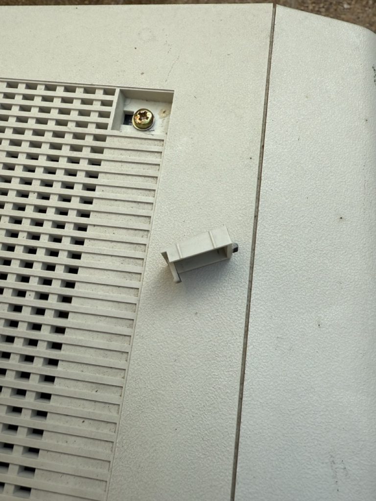
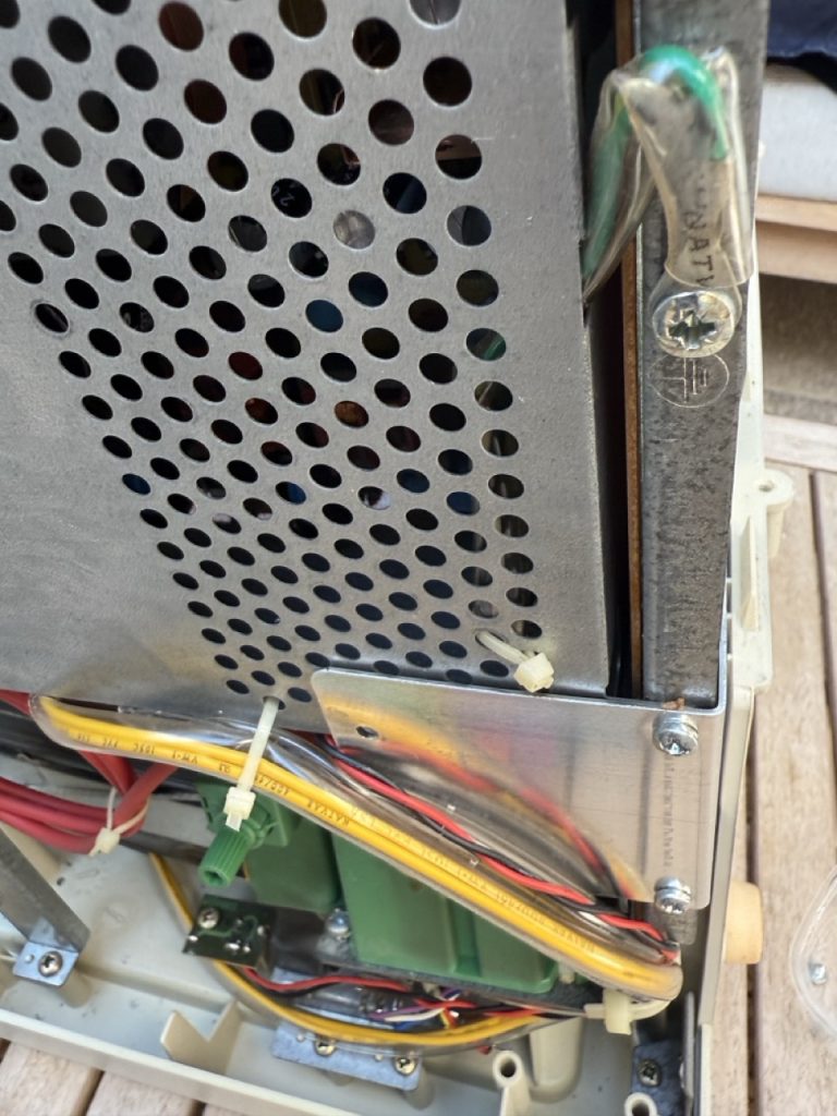
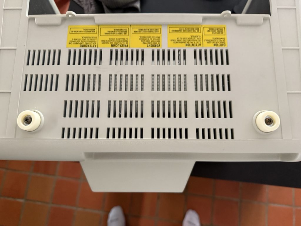
On the top both sides, there is a small plastic cap that needs to be removed before accessing to the screw to be removed. A flat screw driver can do the job, and a gentle push on the plastic caps is enough to remove it
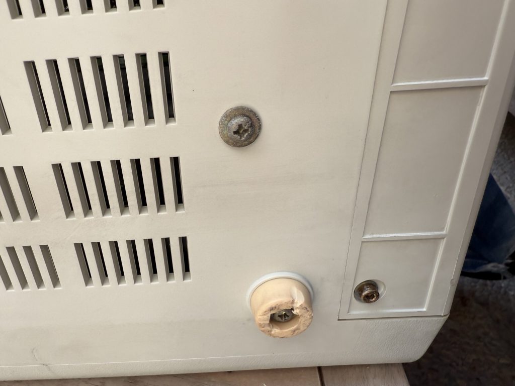
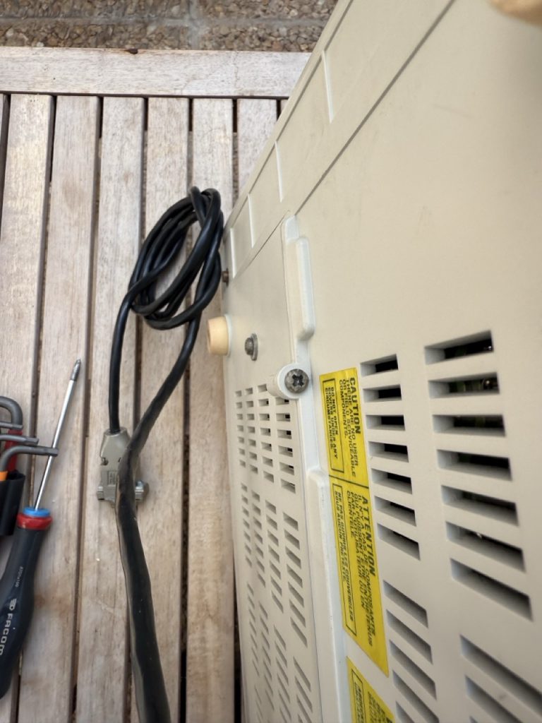
The second set of screws to be removed, are on both side of the yellow stickersThe last ones are on both sides the 3 screws on the below picture.
After opening the case, the PSU (Power System Unit) needs to be removed from the monitor. It is important to bring everything back at the right place at the end of the process, I really encourage to take as many photo as you can to really be able to rebuild it.
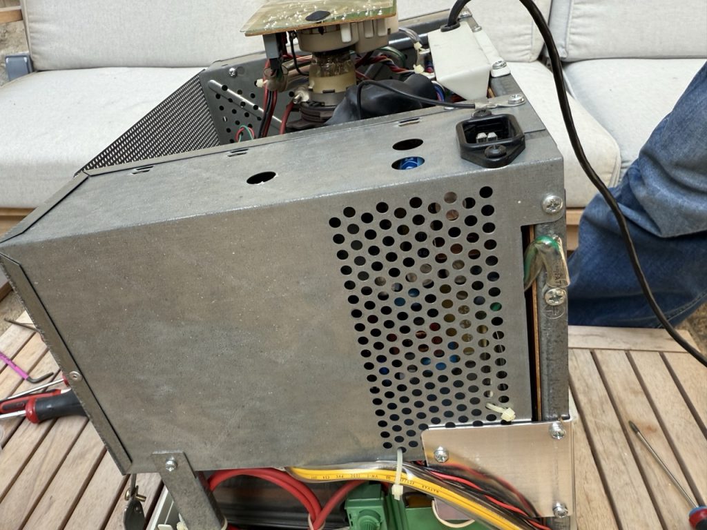
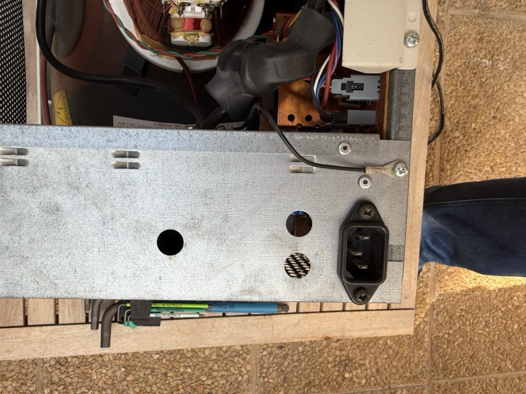
Screws on the PSU need to be removed and also 3 flat head rivet need to be drilled to remove the PSU from the Chassis. Please pay real attention to the connector on the PSU and mark the side before removing them.
After separating the PSU, you should have the following PCB
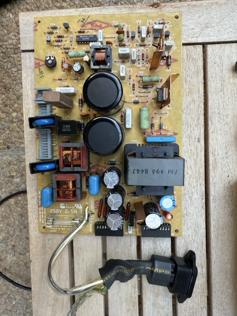
The main issue seats with the electrolytic capacitor and the AC line security capacitor (RIFA like) that are not aging well.
On my PSU board, the following capacitors in red have burnt and thus need a remplacement,
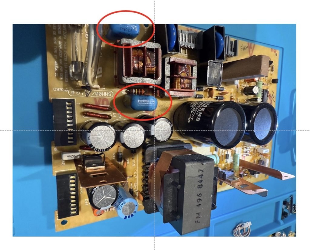
If you plan to change board capacitor the following one needs to be at least tested and replaced to prevent any upcoming issues.

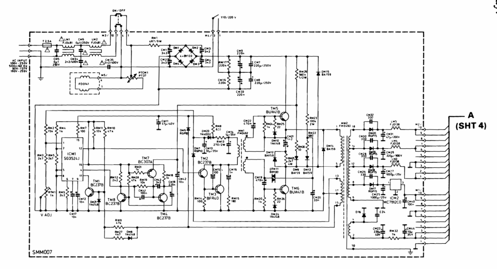
This is the logic diagram of the PSU
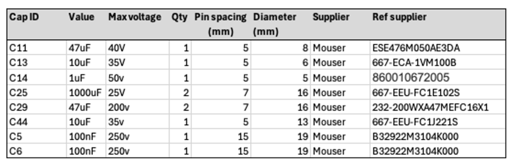
BOM of capacitors to be changed
I have checked and done pretty much the same on the logic board (on the opposite side of the PSU. The main difficulty is that electrolytic capacitors are solder from the top on not at the bottom of the board, there are 12 capacitors 10uF 35v to be checked, and a few others.
After this step, you should carefully put all components back in place and clean up any dust or dirt with the appropriate cotton and isopropyl alcohol. One more time pay attention of the High Voltage rail, do not touch anything with you hand.
At the stage you have the monitor rebuilt with the main plastic case not installed.
Unless you have a PGC card, the next step is to convert this monitor to use classic Video VGA signals with a ISA VGA card.
To do so, we will need to have an extra Hardware component between the monitor and the VGA adapter and also to adjust the potentiometer to modify slightly the vertical and horizontal frequency.
PGC Monitor use to have vertical and horizontal sync signal separated, however there are already the right Red Green Blue signal with each a GND pin. The aim is to build a composite V/H signal for VGA.
This is quite a common and already existing approach using a 74LS86 IC and 2 capacitor / resistor.
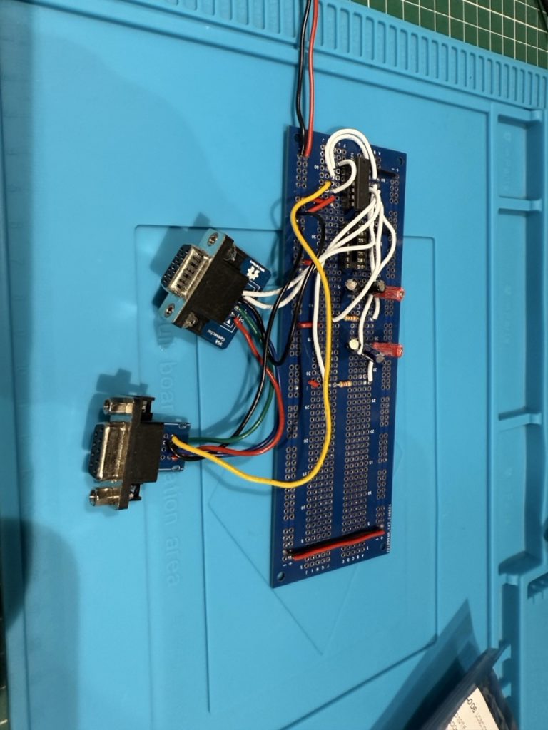
The following schema has been tested and is working :

I did a small experiment before going to final PCB to confirm every was working
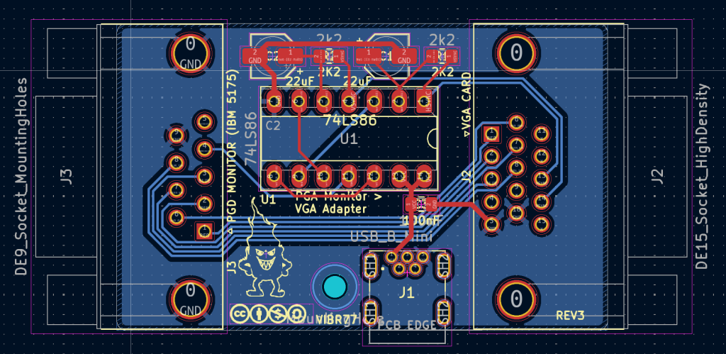
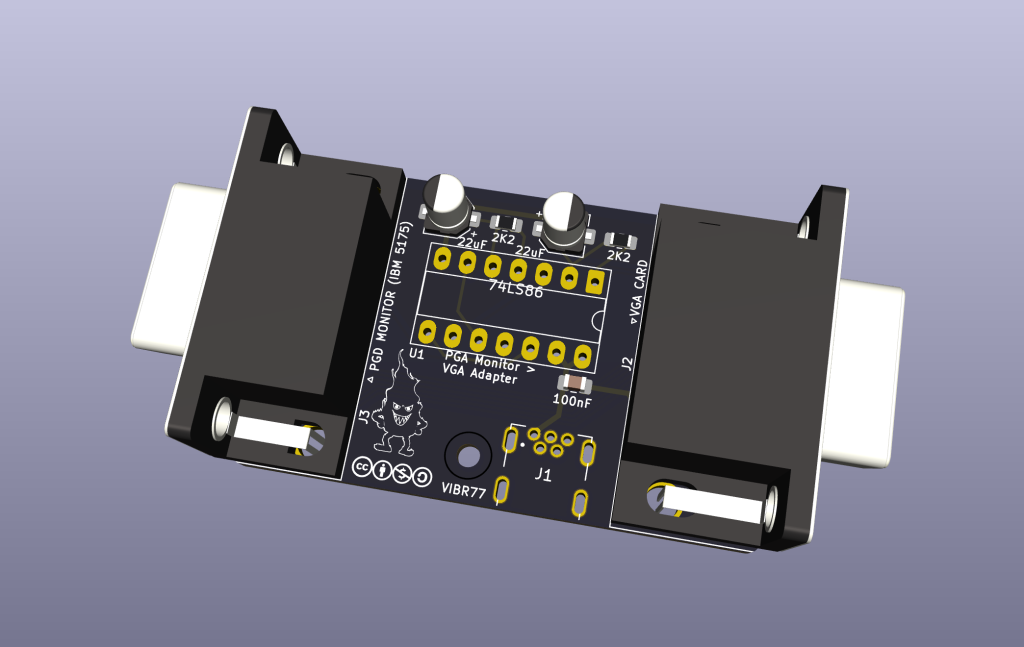
The following PCB can also be used (with easy to solder SMD components
The Kicad project files can be found here:
The 3D view of the PCB gives the following
The BOM for the PGA / VGA Adapter:
The last step for the adapter is to have a proper 3D case that fits perfectly the PCB with a snap on/off top.
I have design a case based on the revision 3 of the board using Fusion360
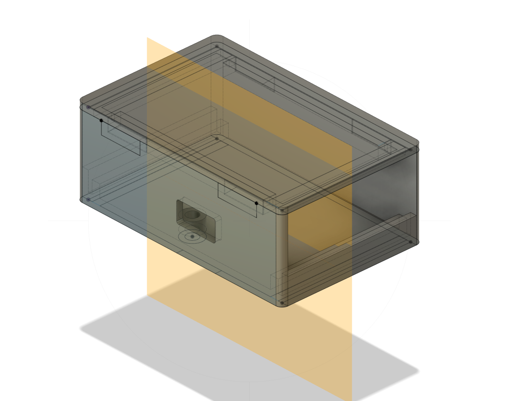
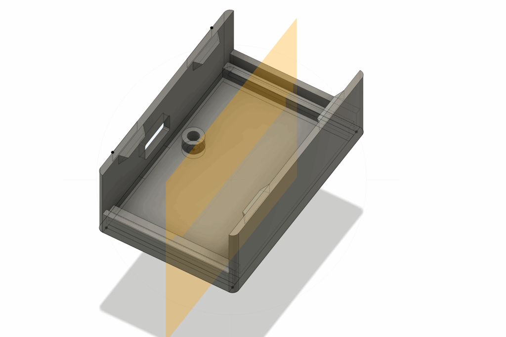
The project files are available here:
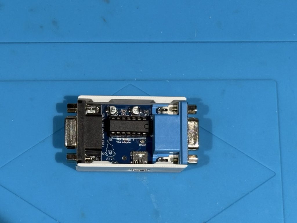
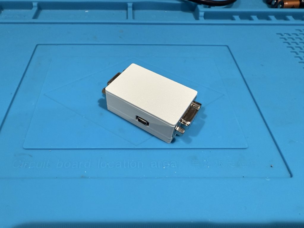
This the final result of the PGA/VGA Adapter
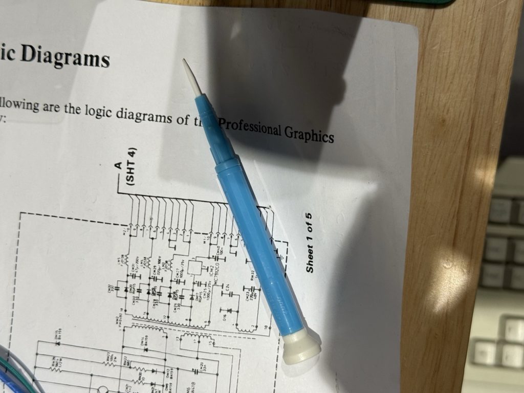
Before reinstalling the main plastic case of the monitor, it is time to adjust the signal vertical & horizontal sync as the PGA does not use the classic 31 Khz sync frequency.
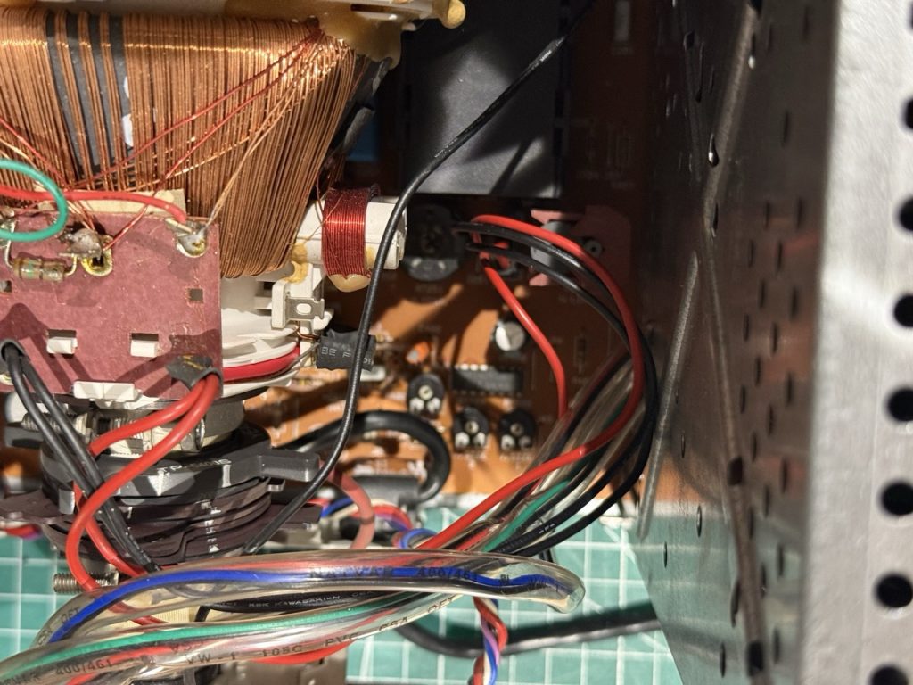
There is a PCB (main pcb) between the PSU and the Logic board, with potentiometer to be adjust. It is more than highly recommended to use Ceramic screw driver to avoid any High voltage issue.
At this stage you have the monitor with the PSU powered, the VGA/PGA Adapter plugged in and the PC providing the correct VGA signal. On the 5175, you should get a scrambled image due to the sync freq adjustment.
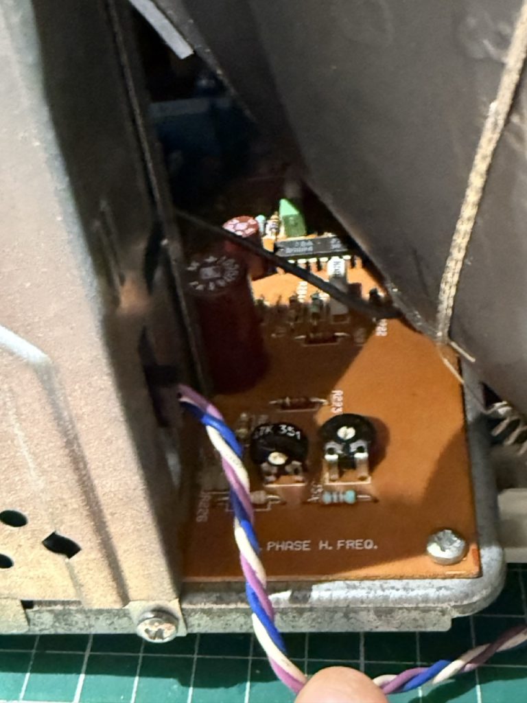
On the main PCB the following potentiometer needs to be adjusted:
Bonus step: on my 5175, I add the small plastic bottom support broken (aging ?), I decided to replace them as well
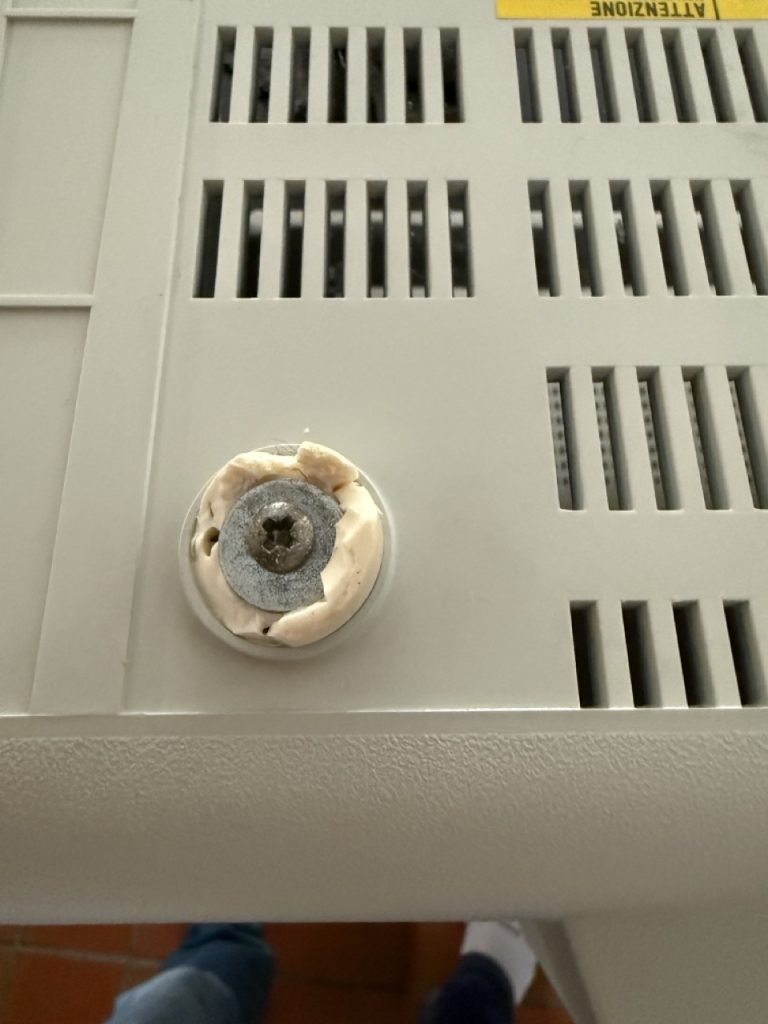
with new one
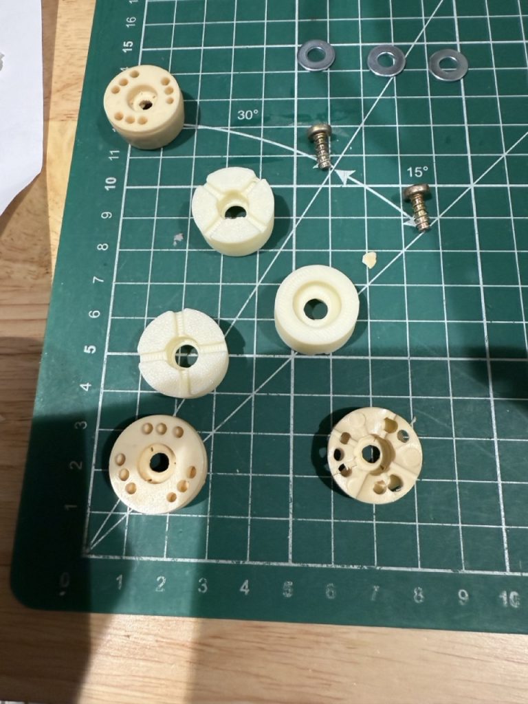
The Fusion 360 file: