Introduction
After hesitating for months, I finally decided to start the WonderMCA project… It is just the beginning of a very long journey to bring MCA Bus based IBM Computer a software defined card like the famous #PICOMEM or the #PICOGUS.
This project has been in my head for many years, and I have postponed it way for too long.
I will be posting here my progress as I expect this journey to be more than a walk in the park…
The story behind this project is pretty simple, it is all about frustration not being able to find MCA extension card available at a decent price. The lack of ongoing project was also a trigger.
What made me hesitate for so long was mainly:
- Scarce / or very little documentation,
- Almost no open project,
- Lack of required skills,
- Complexity of the MCA Beast
Over the last 2 years, I have been working on several projects on the Apple II like the SmartDisk Floppy disk emulator or Smartport card. I have sharpened my skills on using ARM based MCU to interface with antic systems. I have also deeply learned, reviewed code, built my own version of the PicoMem / PicoGus ISA card as a starting point.
I would like to thank FreddyV the author of the PicoMem and also Schlae the author of the Snark Barker (Sound Blaster version for MCA). Both were very kind to bring support in my upcoming adventure and at the same time warning me on the trickyness of this project.
My current playground will be the following:
- IBM 8555 SX
- IBM 8550Z (Zero Wait State)
- IBM 8556 SLX Model 56
- IBM 8557 SLC Model 57
- IBM 8560 Model 60
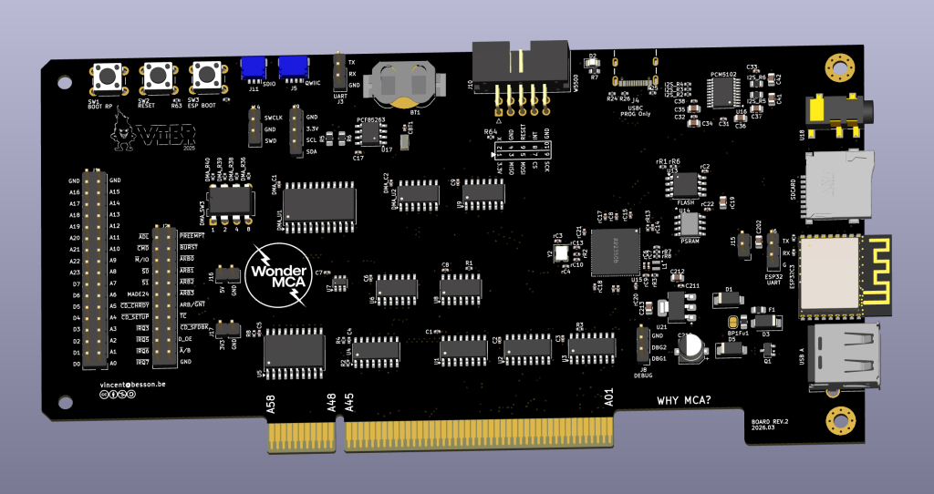
V0 Design
The WonderMCA will start with the following capabilities:
- 24 Bits address line, 8 Bits data line
- Multi Level IRQ 3- 7, DMA Channel 1-3,
- Boot BIOS ROM,
- POS Programmable Option Select,
- HDD Hard Disk Drive emulation based on SD Card Image,
- FDD Floppy Disk Drive Emulation based on SD Card Image,
- Network Emulation (Ne2000) based on WiFi or Ethernet modules,
- Sound Card emulation (SB Pro, Adlib, …),
- RTC Real Time Clock,
- POST Code visualisation on boot for diagnosis,
- External ScreenPad with Rotary switch and button,
With the following main components:
- RP2350B QFN80, ARM dual core, 150 MHz, with 48 GPIOs,
- 8Mb of Flash, 8 Mb of PSRAM
- ESP32C3 for Wifi Module (see my other post on adding WiFi to Raspberry Pico)
- PCF85263 for Real Time Clock over I2C
- PCM5102 for DAC Digital Audio Converter
- A CPLD to manage DMA Arbitration
- SDCard Slot
- Qwiic Slot
- SPI to W5500 extension Module for Ethernet
- 2×25 Pin Header for testing and debugging
Documentation
I use the following documentation on MCA Bus:
- IBM MCA Architecture Handbook By Heath Chet, https://archive.org/details/microchannelarch00heat
- The x86 Interfacing https://archive.org/details/x86pcassemblylan5edmazi
- Ardent-tool https://www.ardent-tool.com, IBM Documentation specification
- Tubetime post on github https://github.com/schlae/mca-tutorial
MCA Bus
The MCA Bus differs from the ISA BUS from many aspects including the form factors, and I will detailed out the physical dimension in a later post when I will start the PCB routing.
Main signals to manage
The following signals will be handled during the design of the circuitry
| MCA PIN | NAME | DESCRIPTION | TYPE | CATEGORY |
|---|---|---|---|---|
| A [37 – 42] | D0 – D7 | Data Lines 0 – 7 | R/W | Data |
| A [4 – 18] | AL0 – AL11 | Address lines 0 – 11 | R | Address |
| B [6 – 20] | AL12 – AL23 | Address lines 12 – 23 | R | Address |
| A20 | /ADL | Address Latch signal | R | Control signal |
| A34 | M/IO | Memory / IO signal | R | Control signal |
| A32 | /S0 | S0 Control signal | R | Control signal |
| A33 | /S1 | S1 Control signal | R | Control signal |
| B34 | /CMD | Data Latch signal | R | Control signal |
| A36 | /CD_CHRDY | Channel Ready (Extra Wait State) | W | Control signal |
| A2 | MADE24 | MADE24 Address width signal | R | Control signal |
| A1 | /CD_SETUP | POS Signal | R | Control signal |
| B36 | /CD_SFDBK | Card Select Feedback | W | Control signal |
| B[22-28] | /IRQ3-7 | IRQ Line | W | Control signal |
| A21 | /PREEMPT | Preempt signal | W | DMA |
| A22 | /BURST | Burst transfer signal | W | DMA |
| A[24-28] | /ARB0- /ARB4 | DMA Arbitration Level | W | DMA |
| A29 | ARB /GNT | Arbitration grant | W | DMA |
| A30 | /TC | Terminal Count | R | DMA |
This is a pretty huge list of signal to handle… this is why the RP2350B with 48 GPIOs will be usefull along with a proper signal multiplexing for address lines and data lines.
Signals description
- / indicates an Active LOW signal*
(n) indicates a MCA slot individula signal
Data Line: this project will be handling only 8Bit data size (Data 0 to 7)
Address Line: the first version of the design will focus only on the 24 bits address lines to be able to handle address range from 0x000000 to 0xFF FFFF, meaning 16 Mb of address space.
/ADL: is the Address latch signal, meaning that the address from the address line is stable and can be latch by the WonderMCA. this signal will be used during the multiplexer to trigger the PIO in charge of the address decoding. It will save ourself a few ns (needed).
M/IO: This signal is active LOW, and differentiate a Memory Bus Cycle to an IO Cycle, When this signal is high, a memory cycle is in progress. When M/-IO is low, an IO cycle is in progress. M/-IO is driven with a tri-state driver
/S0 and /S1: both active LOW, indicate if the cycle is a Read or Write based on the below table:
| Function | M/IO | S0 | S1 | Comment |
|---|---|---|---|---|
| IO READ | LOW | HIGH | LOW | |
| IO WRITE | LOW | LOW | HIGH | |
| N.C | LOW / HIGH | LOW | LOW | Reserved |
| N.C | LOW / HIGH | HIGH | HIGH | Reserved |
| MEM READ | HIGH | HIGH | LOW | |
| MEM WRITE | HIGH | LOW | HIGH |
Note: MCA is more frugal than ISA that is using 4 lines (MEMR,MEMW,IOR,IOW) instead of 3 for MCA (M/IO, S0,S1)
Note: there is no exemple of S0 & S1 being LOW or HIGH at the same time
/CMD: the Equivalent of the /ADL but for DATA, it is the Data latch signal, where the data is available on the bus or READ or WRITE. This signal is used to define when data is valid on the data bus. The trailing edge of this signal indicates the end of the bus cycle. This signal indicates to the slave how long data is valid on the bus. During write operations, the data is valid on the bus as long as /CMD is active. During read operations, the data is valid on the bus between the leading and trailing edges of /CMD, and must be held on the bus until after -CMD goes inactive.
/CD_CHREADY: This is the equivalent of IO_CHREADY for the ISA bus, it enable the slave card (aka WONDERMCA) to request extra cycle to be able to finish the READ/WRITE operation.
MADE24: is really specific to the MCA BUS, this lines indicates if the current address on the bus is higher than the 16MB address spaces, this is an active HIGH signal. When the signal is LOW then the address space is 32 Bits. MADE24 is driven by a 3 state Driver. This line will be help full to discard any address above the 24 Address line in the address space range of 0x00FF FFFF – 0xFFFF FFFF.
/CD_SETUP: this line indicates that POS (Programmable Option Select) phase is active to access the POS register on the slace. This signal is unique to each channel connector (not shared across all MCA slot but specific and individual). This signal is active LOW and driven by a totem-pole driver.
/CD_SFDBK: Card Select Feedback, when the MCA Bus Master (the CPU most of the time) is addressing a slave device like the WonderMCA.The addressed slave device /CD
SFDBK active as a positive acknowledgment of its presence at the address specified. This signal is unique to each channel connector (not shared across all MCA slot but specific and individual).
IRQ3-7: Interrupt Request: These lines are used to signal that a device requires attention. They are prioritized with -IRQ 9 having the highest priority and -IRQ 7 having the lowest priority.
ARB0 – ARB3: Arbitration Bus Priority Levels, these lines comprise the arbitration bus and are used to present priority levels for participants seeking control of the bus. ARBO through ARB3, the least-significant through most-significant bits respectively, support up to 16 priority levels.
ARB/-GNT: Arbitrate/-Grant: When high, this signal indicates an arbitration cycle is in process. When low, it is the acknowledgment from the central arbitration control point to an arbitrating bus participant (local arbiter) and the DMA controller that channel control has been granted.
/PREEMPT: -Preempt: This signal is used by arbitrating bus participants (local arbiters) to request use of the channel through arbitration. Any local arbiter with a channel request activates -PREEMPT and causes an arbitration cycle to occur. A local arbiter removes its -PREEMPT upon being granted the channel. This bidirectional line must be driven with an open collector driver.
/TC: Terminal Count serves the same purpose as the ISA BUS DMA Controller, It indicates that the current DMA transfer count has been reached. It is driven with a tri-state driver by the DMA controller.
/BURST: This signal indicates to the DMA controller the extended use of the channel for transferring a block of data. This type of data transfer is called a burst cycle. This line is shared by all local arbiters. /BURST is driven active by the local arbiter after being granted the channel. The local arbiter must deactivate -BURST during the last transfer cycle. /BURST must be driven with an open collector driver.
Note: I have no clue how to integrate this one, let’s see…
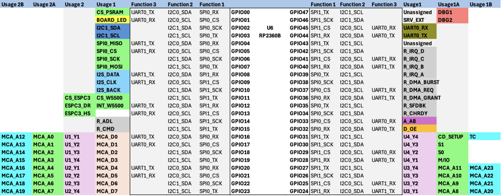
Signal Multiplexing & Level Shifting
Even if the RP2350B has 48 GPIOs, frugality will be an important point not to waste GPIOs and ensure system speed & agility. Another aspect is the Signal Level Shifting, the RP2350B is handling signal level from 0v LOW to 3V HIGH, and the MCA Bus is working on a 5V basis. Thus level shifter will be important to convert 5V to 3V and to avoid RP2350 damages.
Signal Multiplexing:
As GPIOs are not unlimited on the RP2350B, A proper signal multiplexing will be managed to decode Address Line / Control Line / Data line signal.
this is it for this first post
to be continued