
SmartDisk II · User documentation · Latest firmware
The SmartDisk II board and its XL variant, the connectors and power jumpers, how to connect it to an Apple II, IIc, IIgs or Macintosh, which emulation to pick for which connection, and what to check before the first power-up.
← SmartDisk II documentation home · Page 2 of 16
This page shows you what is on the board, how it is powered, how to connect it to your computer and what to check before you switch it on.
Warning. Never connect the ST-Link programmer at the same time as USB or the Apple II. Its voltage regulator is fragile. The silkscreen of the board says ONLY 1 PWR SRC (3V, 5V, SDIO 3V): use one power source at a time. See “Power”.
What you get
The SmartDisk II is one printed circuit board, 76.0 x 56.35 mm, with these parts:
| Part | What it is |
|---|---|
| Microcontroller | STM32F411 “BlackPill” module, plugged on the board |
| Display | 0.96 inch OLED module, 128 x 64 pixels, I2C (1.54 inch on the XL board) |
| Storage | microSD socket, push-push, with a card-detect contact |
| Keys | Four keys: UP, DOWN, ENTER, RET. On the XL board a rotary encoder replaces UP and DOWN |
| Reset | The NRST button of the BlackPill module |
| Buzzer | 12 mm buzzer: key click, eject and insert sounds, failure sound |
| Drive connector | 2 x 10 pin IDC header J2 (“APPLE_SDISKII”): the ribbon cable to the Apple II |
| USB | The USB connector of the BlackPill module. You use it to update the firmware (see page 04) |
Revisions
| Revision | What it is |
|---|---|
| 8 | Through-hole keys and connector, soldered by hand. Its gerber files are available on GitHub |
| 9, SMD | The surface-mount keys and connector are placed by machine. The BlackPill, the OLED and the buzzer are fitted by hand |
| 9, through-hole | Same board as revision 9 SMD, with a through-hole IDC header and through-hole keys, in the same positions as revision 8. It adds a 1N4148 diode D1 in parallel with D2 |
| 10, XL | The SmartDisk II XL: a 1.54 inch OLED and a rotary encoder in place of the UP and DOWN keys. See “The XL board” |
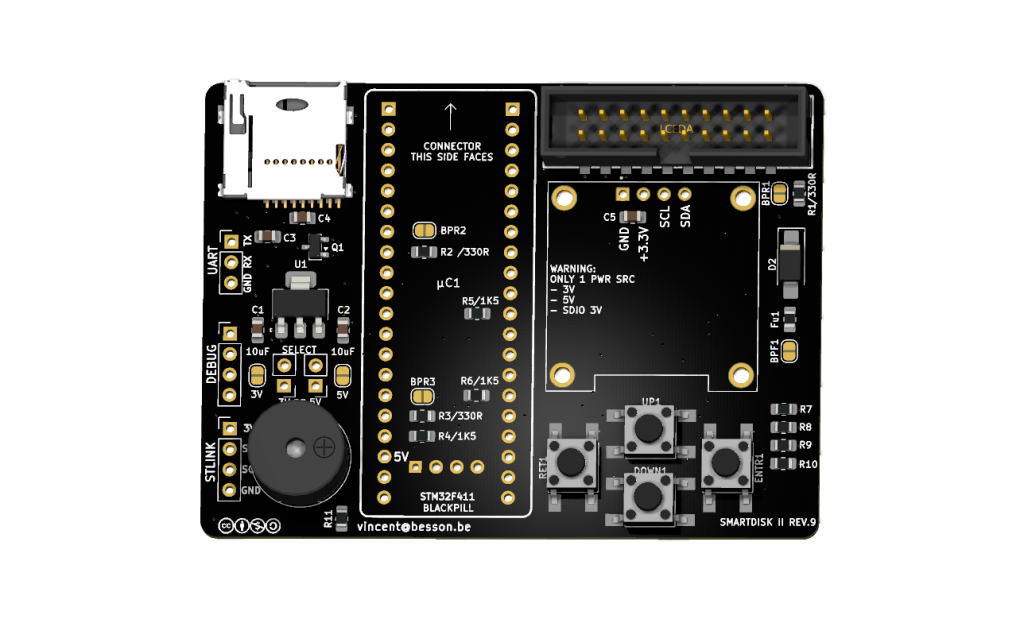
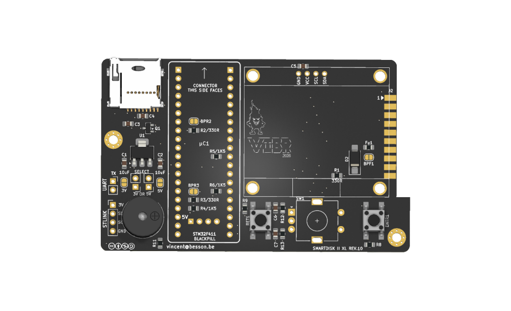
The XL board needs its own firmware image (page 04).
Rev9 Not released yet on GitHub, What revision 9 changes against the earlier boards:
- Additional decoupling capacitor for SDCard and OLED,
- Additionnal resistor especially on PA0 (not 5V)
- Complete new routing
- New LDO to replace power rail on the board,
- New Buzzer decoupling to protect the blackpill
The XL board
Not released yet on github, The SmartDisk II XL (revision 10) is the revision 9 SMD board with two changes:
- A 1.54 inch OLED (SSD1309) instead of the 0.96 inch one.
- A rotary encoder with a push switch instead of the UP and DOWN keys.
How you use the encoder:
| You do | The board sees |
|---|---|
| Turn clockwise, one click | DOWN (one entry down) |
| Turn counter-clockwise, one click | UP (one entry up) |
| Press the knob | ENTER |
The ENTER and RET keys stay on the board and work as before: ENTER and the push of the encoder do the same thing. A turn of the knob replaces a held UP or DOWN key: to go down a long list, keep turning.
The rest of the board is the same as revision 9: the same connector, the same power jumpers, the same SD socket. Differences you may notice:
- There is no 0.96 inch OLED, no UP and DOWN key and no
J5debug header. - The bypass pad
BPR1does not exist:R1stays in the circuit. - The UART header
J4has two pins: TX and GND.
The XL board runs the XL firmware, and the standard board runs the standard firmware. Check which file you download (page 04).
The connectors and solder pads, one by one
This section describes revision 9 (SMD and through-hole). The XL board has the same pads, except where “The XL board” above says otherwise.
| Ref | What | What it does |
|---|---|---|
J2 | 2 x 10 IDC header, “APPLE_SDISKII” | The cable to the Apple II (and, with an adapter, to the IIgs and Macintosh ports). The pin table is below |
J1 “PWR”, silkscreen 5V | 1 x 2 pin header | Pin 1: the 5 V pin of the BlackPill. Pin 2: the Apple 5 V after the fuse and the diode. A jumper here joins them. The solder pad JP1 makes the same connection |
J7 “PWR”, silkscreen 3V | 1 x 2 pin header | Pin 1: the 3.3 V rail of the board (OLED, SD socket, pull-ups, the 3.3 V pins of the BlackPill). Pin 2: the output of the board regulator U1. A jumper here feeds the rail from U1. The solder pad JP2 makes the same connection |
J4 “UART” | 3 pin header (2 pins on the XL board) | TX, RX, GND: the console log of the firmware, 460800 baud, 3.3 V levels |
J5 “DEBUG” | 4 pin header (not on the XL board) | Test points for a logic analyser |
J6 “STLINK” | 4 pin header | 3V, SDIO (SWDIO), SCK (SWCLK), GND: the ST-Link programmer |
BPF1 | solder pad, open | Bypasses the fuse Fu1 |
BPR1, BPR2, BPR3 | solder pads, open | Each bypasses one 330 ohm series resistor: R1 on WR_PROTECT (pin 20), R2 on the 3.5 inch select line (pin 7), R3 on SELECT (pin 12) |
D2 | SS54 diode | In series after the fuse |
Fu1 | resettable fuse, 750 mA | In series on the 5 V that comes from the drive connector |
Notes:
- The pin headers
J1,J4,J5,J6,J7and the solder pads are not fitted by the assembly house: you solder them if you need them. - All solder pads are open as designed. Leave the bypass pads open unless you know why you close them.
- The 330 ohm resistors protect the lines that the Apple II writes on (pins 7 and 12) and the one the board drives (pin 20).
The 20 pin header J2
| Pin | Signal | Role |
|---|---|---|
| 1, 3, 5 | GND | ground |
| 2 | STEP0 (phase 0) | head stepper phase 0; SmartPort PH0; 3.5 inch CA0 (through 1.5 kohm) |
| 4 | STEP1 | phase 1; 3.5 inch CA1 |
| 6 | STEP2 | phase 2; 3.5 inch CA2 |
| 7 | 3.5DSK | the 3.5 inch drive select (low when a 3.5 inch drive is addressed) |
| 8 | STEP3 | phase 3; 3.5 inch LSTRB |
| 10 | WR_REQ | write request |
| 11 | VCC | +5 V from the Apple II |
| 12 | SELECT | SEL on the 3.5 inch port |
| 14 | DEVICE_ENABLE | drive enable (active low) |
| 16 | RD_DATA | read data (on a Macintosh also the status line) |
| 18 | WR_DATA | write data |
| 20 | WR_PROTECT | write protect (on the 3.5 inch port: the sense line; on a Macintosh an input to the drive) |
| 9, 13, 15, 17, 19 | not connected |
Power
The 5 V of the Apple II arrives on connector pin 11 and goes through the fuse Fu1 (750 mA) and the diode D2, then to the 3.3 V regulator U1 (TLV1117LV33). The regulator accepts at most 5.5 V: never feed the power pins with more.
The BlackPill has its own regulator and its own USB connector. Its 5 V pin and its 3.3 V pins are what the two jumpers connect to.
The text printed on the board:
WARNING:
ONLY 1 PWR SRC
- 3V
- 5V
- SDIO 3V
“3V” is the J7 / JP2 pair, “5V” is the J1 / JP1 pair and “SDIO 3V” is pin 1 of the ST-Link header J6. The board takes one power source at a time.
| Situation | What to do |
|---|---|
| Running in the Apple II or the Macintosh | The computer is the only source. Close one of the two pairs: J1 / JP1 (“5V”: the Apple 5 V feeds the BlackPill, which makes its own 3.3 V) or J7 / JP2 (“3V”: the regulator U1 makes the 3.3 V for everything). Never close both |
| Updating the firmware over USB | USB is the only source: take the board out of the computer and remove the jumpers on J1 and J7 |
| Flashing the bootloader with an ST-Link | The ST-Link is the only source: no USB, no Apple II, no jumpers on J1 and J7 |
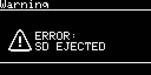
A power-up without a card is safe: the board shows SD EJECTED and waits for the card.
What you need
| For | You need |
|---|---|
| Every machine | A microSD card prepared as on page 03, and a 20 conductor ribbon cable with a 2 x 10 socket for J2 |
| II+, IIe (Disk II emulation) | A Disk II controller card in a slot (slot 6 to boot), and the ribbon from the drive connector of that card to J2 |
| II+, IIe (SmartPort emulation) | A card that speaks SmartPort: Liron, SoftSP6 or Yellowstone |
| IIc, IIgs | A cable from the drive port (DB-19) of the computer to the 20 pin header, wired as the table of J2 above |
| Macintosh | A cable from the external floppy port (DB-19) to the 20 pin header |
| Firmware work | A USB cable for the BlackPill. An ST-Link programmer only to install the bootloader the first time (page 04) |
Three lines of the Macintosh floppy port are worth knowing when you make a cable:
| DB-19 pin | Header pin | What it does |
|---|---|---|
| 4 | 7 | ground on a Macintosh (so the select line reads low) |
| 10 | 20 | an input to the drive on a Macintosh: the board never drives it |
| 17 | 14 | the external drive enable |
On the Macintosh the status line moves to the read data pin (header pin 16). All the other lines are used as for the IIgs.
Pin 1 of J2 is a ground pin. Match the marked wire of the ribbon (the red one) to pin 1 and check the cable against the table above before you power anything.
Installing it in each machine
Always: the Apple II or Macintosh is off, the board has no other power source, and you insert the card last. Switch the computer off before you plug or unplug the cable.
Apple II+, II Europlus, IIe, with a Disk II controller card
- Switch the computer off.
- Plug the ribbon onto the drive connector of the Disk II controller card (slot 6 to boot from it) and onto
J2of the board. - Set the power pair for the computer as described in “Power”.
- Insert the SD card, then switch the computer on.
- The splash and then the main menu appear on the OLED. In Settings, choose the emulation type Disk II if it is not the one in use. A card without a configuration file starts with Disk II.
- Mount an image from the file manager and boot the computer (Disk II emulation (5.25 inch)).
The same firmware and the Smartloader work on a stock IIe.
With a SmartPort card in a II+ or IIe (Liron, SoftSP6, Yellowstone)
Proceed as above, with the ribbon on the connector of the SmartPort card, and choose the emulation type SmartPort HD in Settings (SmartPort emulation (hard disk)).
Apple IIc
- Switch the IIc off.
- Connect the board to the external drive port (DB-19) of the IIc.
- Choose Disk II or SmartPort HD emulation (08, 09).
The IIc ROM 4 is supported.
Apple IIgs
- Switch the IIgs off.
- Connect the board to the disk port (DB-19) of the IIgs.
- Choose the emulation: Disk II (5.25 inch port), SmartPort, Smartloader, or the 3.5 inch drive (08, 09, Smartloader, 3.5 inch drive emulation (IIgs and Macintosh)).
A IIgs ROM 03 boots Disk II images, SmartPort images, the Smartloader and 3.5 inch images from the DB-19 port. The IIgs asks the SmartPort bus before it boots a 5.25 inch disk: the Disk II emulation ignores its own enable line then, so you do nothing special.
Note. A IIgs with an accelerator card can write to a Disk II image with a timing that is off by one cycle. If writes fail on one machine only, run the IIgs at normal speed first.
Macintosh with an external 800K floppy port
- In Settings, set the emulation type to Disk 3.5.
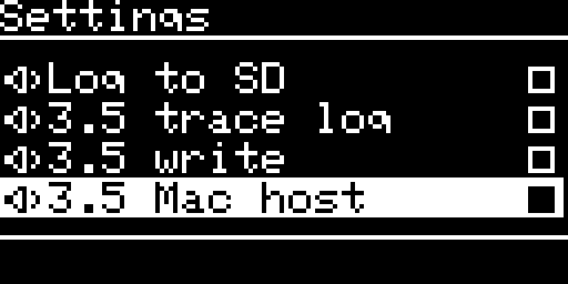
- Switch 3.5 Mac host on. ENTER on it asks (ENTER: host+reset). ENTER again saves it and the SmartDisk II restarts. The setting changes how the board drives its pins and is read when the emulation starts.
- Switch 3.5 write on only if the Macintosh should write to the image.
- Mount an image (
.dc42,.2mg,.po,.imgor.moof) from the menu. - Switch the Macintosh off and connect the board to the external floppy port (DB-19). To start from the image, start with the internal drive empty: a Macintosh looks at its internal drive first.
- Switch the Macintosh on.
A Macintosh SE on its external drive port sees the drive, reads an image, and can write to it: Initialize of a blank 800K image completes. An HFS image made with Create disk is recognised.
The setting 3.5 SuperDrive (experimental) is in the same list when 3.5 Mac host is on. It makes the board answer as a SuperDrive, for 1.44 MB images on Macintosh models whose ROM supports one. ENTER asks, then saves and restarts the board.
The Macintosh mode, the eject and the images are described on 3.5 inch drive emulation (IIgs and Macintosh).
HD20 emulation (Macintosh): upcoming. It is not available in this firmware yet. The list of emulation types already shows an HD20 (Mac) entry: do not choose it, it does not work yet.
Which emulation for which connection
| You connect to | Choose in Settings, Emulation type | Page |
|---|---|---|
| II+, II Europlus, IIe, Disk II controller card | Disk II | 08 |
| II+, IIe, SmartPort card | SmartPort HD | 09 |
| IIc (external drive port) | Disk II or SmartPort HD | 08, 09 |
| IIgs, 5.25 inch boot | Disk II | 08 |
| IIgs, hard disk volumes | SmartPort HD | 09 |
| IIgs, browse and boot from the Apple II screen | Smartloader | 10 |
| IIgs, 3.5 inch drive | Disk 3.5 (3.5 Mac host off) | 11 |
| Macintosh external 800K port | Disk 3.5 with 3.5 Mac host on | 11 |
The Smartloader works on the IIe and the IIgs (10).
The case
The project has the files of a 3D printed case: a body in two variants (one for a high buzzer, one for a low buzzer), a top, a screen template, a navigation key, a key and a reset key, and the Fusion 360 file of the whole case.
Building it yourself
The gerber files of revision 8 are available on the project page on GitHub: https://github.com/vibr77/AppleIIDiskIIStm32F411.
You fit the BlackPill module, the OLED module and the buzzer by hand.
A new board needs the bootloader first (with an ST-Link on J6), then the firmware over USB: Firmware update.
Before the first power-up
- One power source. Only one of
J1/JP1,J7/JP2closed, as the silkscreen says. No ST-Link, USB and Apple II together. - The OLED. The module pins on the board are in the order GND, +3.3V, SCL, SDA. Some OLED modules have the supply pins in the other order: compare your module with the silkscreen before you plug it in.
- The cable. Check the orientation of the ribbon on
J2and on the Disk II controller card. - The card. FAT32 with 32 KB clusters, or use Make filesystem (The SD card). Without a card the board shows
SD EJECTED. - On a board you built. Look for solder bridges on
J2and on the BlackPill pins. Check with a multimeter that the 5 V and 3.3 V rails are not shorted to ground. Check the diode and the fuse.
At the first start you see the splash with the logo and the version, for about half a second, then the main menu.
A card without a configuration file gets a new sdiskConfig.json with the defaults: emulation Disk II, start at the menu (not on the last image), no sound, no screen saver, “5.25 write” on.

If the display shows Warning, ERROR: SD EJECTED, the card is not detected:
Then see Troubleshooting, FAQ and the log. The screens and keys are on Usage guide and OLED screens reference.
← Previous
Next →
SmartDisk II user documentation · latest firmware · Documentation home