Why this was hard
When I started WonderMCA — a PicoMEM-style RP2350-based card for the IBM PS/2 MCA bus — the obvious “killer app” was Sound Blaster emulation. FreddyV has worked hard to bring the PicoMEM a working SBDSP emulator for ISA Bus; on MCA we get the same software base.
Except for one little detail: the DMA.
The whole point of a Sound Blaster emulation is that it streams 8-bit PCM sample data from RAM to the DAC without the CPU babysitting every sample. That stream goes through DMA (Direct Memory Acces). On an ISA Sound Blaster the DMA is pretty simple — there’s a single 8237 DMA controller on the chassis, you wire the card’s DREQ/DACK pins to one of its channels, and the controller’s hardware does the rest. Total mental load: 30 seconds.
MCA is not ISA. MCA has no 8237. MCA has CACP.
MCA is not ISA. MCA has no 8237. MCA has CACP.
The Central Arbitration Control Point is what IBM substituted for the 8237 when they designed MCA in 1987 — a fully multi-master bus arbiter. Every device that wants the bus (including CPU, refresh, floppy controller, DMA-using card) participates in a 4-cycle priority arbitration. The winner gets the bus for one or a handful of cycles, then has to release. There’s a per-arbitration 7.8 µs deadline: if a card holds the bus longer than that, the chassis fires NMI POST 113 and the OS halts. Trust me I know pretty well the error 113. On MCA Bus, DMA is complex, picky, undocumented, specific to PS/2 model. A pure concentrate of nightmare to have something to work.
In the WonderMCA case, the Sound Blaster emulation will be managed with our card to be DMA Slave (and not DMA Master). It means that the WonderMCA never owns the BUS, it request and capture. simple no ?
On the WonderMCA, we have the following actors:
- The CACP – Central Arbitration Control Point on the chassis
- The MCA Bus – with the Address line, Data line, and control lines,
- The WonderMCA CPLD
- The WonderMCA Control SW (4xDIP Switch)
- The Wonder MCA RP2350B
After many (many many) attempt, and RP2350 PIO trial, I decided to shift from pure RP2350 and to combine it with a CPLD. The Arbitration process is not complex but combinational and requires a processing time that the RP2350 can not provide without losing the MEM / IO Path.
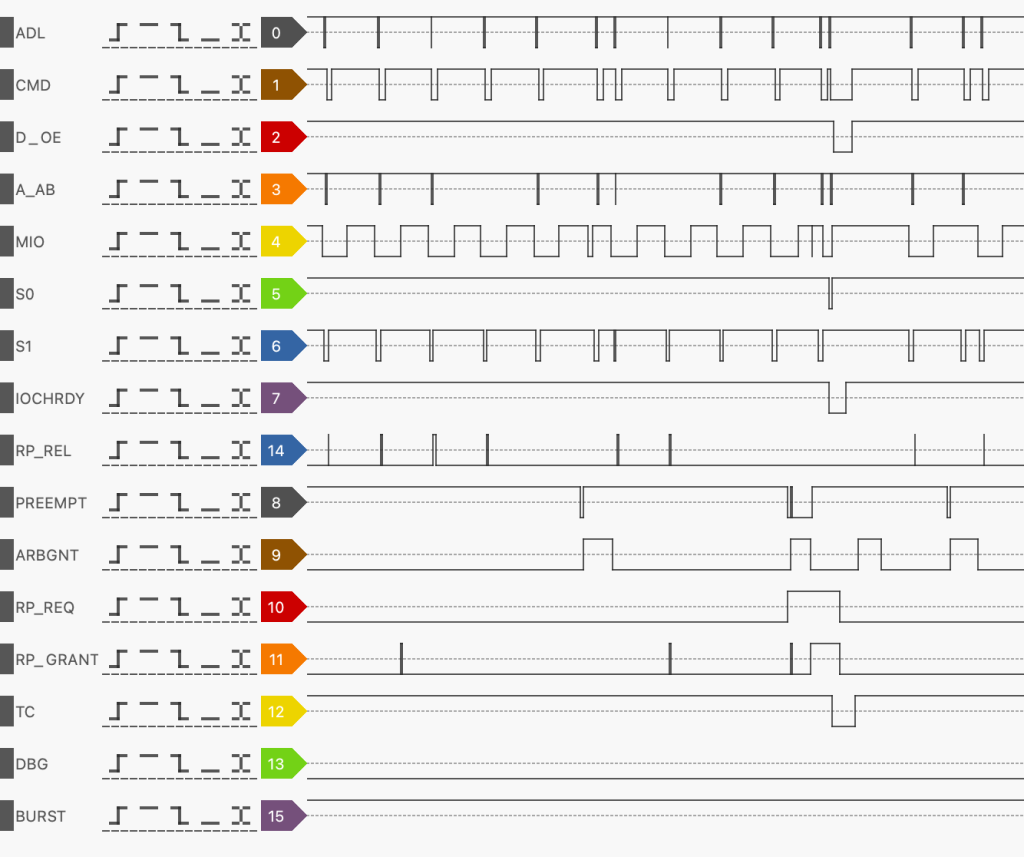
I started a small proof of concept with and ATF22V10C, with the algorithm provided in the IBM specifications. Using my preferred Logic analyser, I was able to see the mecanism of the arbitration.
Given the need for CHRDY signal based on Address line decoding, tight timeframe for raising from M/IO, S0, S1, I decide to combined both CHRDY and DMA in a single CPLD with enough macrocell for my needs.
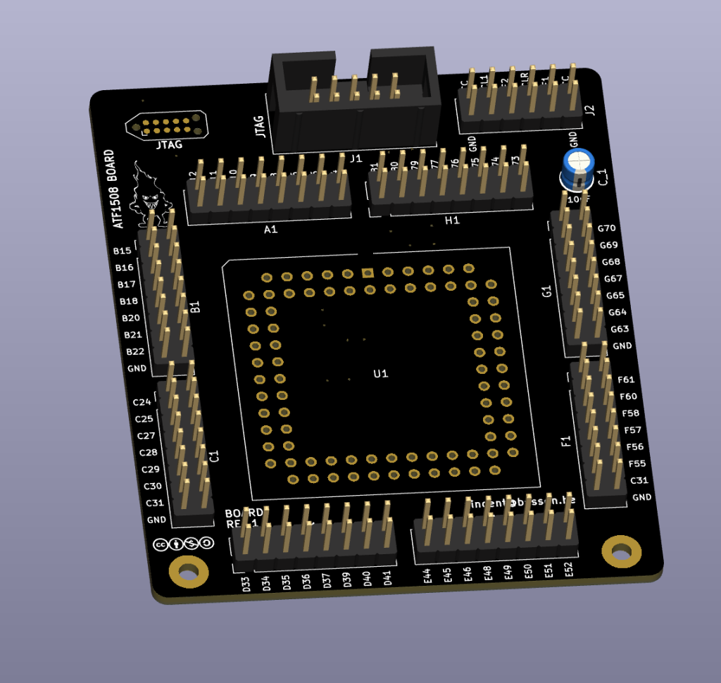
The CPLD would provides enough GPIO (macrocells) to manage: 24x Address lines, 16 MCA Bus signals (/ADL, /CMD, M/IO, /S0, /S1, /PREEMPT, ARB/BNT, MADE24, SBHE, CHRDY, ARB0-3, BURST, TC), and interfaced GPIO between the RP2350. Plus I need a CPLD easy to reprogram meaning with dedicatd GPIO. Last but not least, we need a CPLD 5V compliant.
Putting all this into the shaker and you get very few option, and one good option is the ATF1508 that exist in PLCC84 format. The bad news, it is not produced anymore or difficult to source.
ATF1508 and a TagConnect 2050 is the perfect combo to be able to reprogram the CPLD using WinCUPL without removing the CPLD from the WonderMCA.
The ATF1508 exists in 7ns, 10ns, 15 ns, 20ns, 25ns grade. After doing some test, beyond 10ns on some chassis (IBM P70) you start getting mis assertion of CHRDY.
I bought a stock of ATF1508-10 on aliexpress that seems to work so far…
Going back to the DMA process, this is the step performed between the PS/2 and the WonderMCA:
- The system, like PrinceOfPersia is programming the DMA Controller and provides a buffer in memory,
- It starts the Sound Blaster Emulation by issuing via IOW on port 0x220 CMD to be executed,
- The WonderMCA triggers a DMA request to get the next Byte on the buffer at 22 KHz frequency, roughly ~45 µs,
- The WonderMCA RP2350 assert /RP_DMA_REQ (Interfaced GPIO between the RP2350 and the ATF1508),
- The CPLD assert /PREEMPT when not in /CMD phase, not in ARBITRATION phase,
- The CPLD waits for /ARB_GNT to go High (Arbitration phase)
- The CPLD starts the arbitration providing ARB0-3 signal on the bus based on the 4xDIP switch configuration to enable DMA Channel 1-4
- The CPLD wins the arbitration, and deassert the /PREEMPT signal,
- The Chassis goes in grant phase /ARB_GNT low
- The Chassis starts a IOW cycle
- The CPLD assert /CHRDY
- The RP2350 capture the bytes, important to notice that there is no address lines signal on this IOW cycle,
- The RP2350 release /CHRDY via /RP_REL signal to the CPLD
- The RP2350 release /RP_DMA_REQ,
Sounds simple, on the paper yes, but in reality it is more than painful. Every single timing mistake or /CHRDY holding the bus too long trigger a NMI… What is funny with error 113 (DMA timeout), it wait for the current DMA cycle end to trigger, so you never know which DMA req has pulled the trigger… If you keep /PREEMPT more than 50 ns asserted after the GRANT phase -> 113. And there are tons of undocumented case like these ones. And every error 113, you have to do a cold start, boot the system, prepare for the test and do it again and again… Nice ride.
That’s what we had to build, in hardware (CPLD), firmware (RP2350), and just enough copper on the PCB to make it all reach the bus.
The architecture
Early on we made a key design call: the CPLD handles arbitration,
the RP2350 just streams data.
The RP2350 is a 150 MHz dual-core M33 with PIO. It’s plenty fast for sustained 22 kHz audio (≈45 µs per sample = 6750 PIO cycles), but its GPIOs are way too slow to participate in MCA’s nanosecond-scale arbitration timing directly. The ATF1508 CPLD is a 10 ns PLD — perfect for handshakes; awful for streaming.
The first PCB version of the WonderMCA has to ATF1508-10 and no PLCC84 footprint… However I put MCA Bus signal replication via pin-header on the side of the board. This is not ideal in term of capacitance, but very useful (mandatory) to debug via Logic Analyzer.
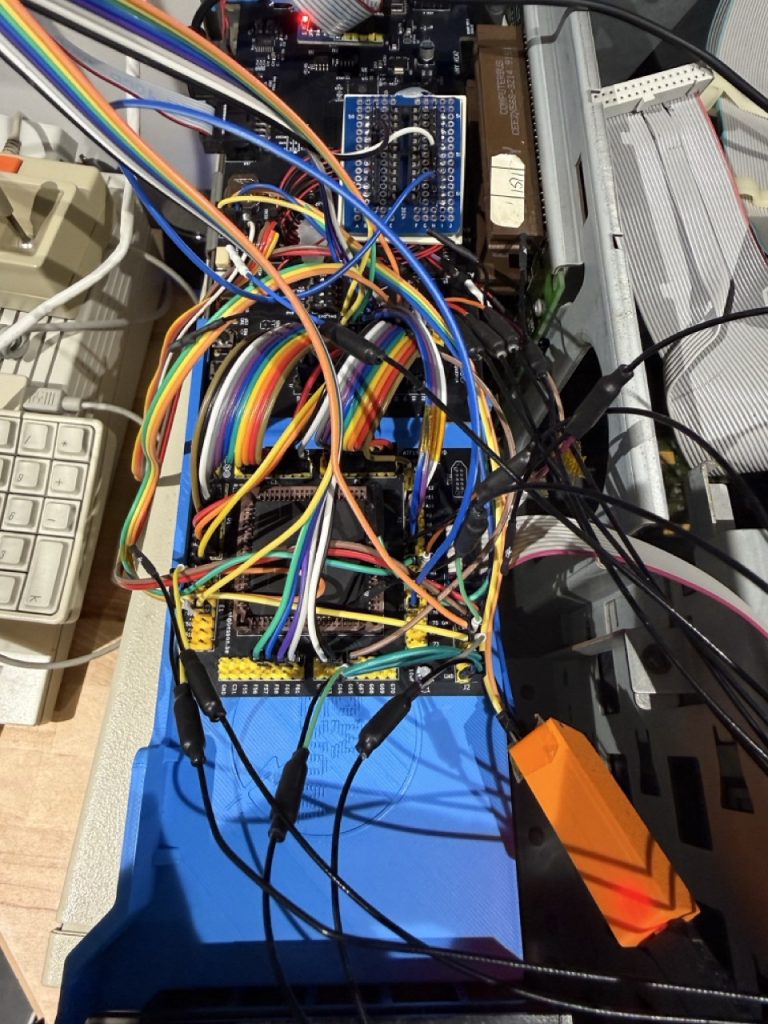
To validate the use of the CPLD, I have create a small daughter board and asked JLCPCB 5x sample. I bridged the pin Header with the daughter board. I had to put a few bodge wire between the RP2350 and the CPLD.
The first prototype now looks like a spaghetti plate and I have time to time connectivity issues, but still good for testing.
Division of labor:
- CPLD: watch the sample-rate timer fire (via
RP_DMA_REQ), raise/PREEMPT, drive arbitration code, claim grant, drive/ADL//CMDfor one IOR/IOW cycle, release. - RP2350: on each cycle the CPLD opens, present the next sample byte (for SBDSP playback) or capture the byte (for ADC).
That keeps the latency-critical handshake inside 10 ns silicon and the bulk-data path in software. Clean.
Three GPIOs link the two:
RP_DMA_REQ(out): RP2350 raises HIGH when it wants the next byteRP_DMA_GRANT(in): CPLD pulses HIGH when arbitration winsRP_TC(in): CPLD pulses HIGH at terminal count
Bodge wire #1 — /PREEMPT doesn’t go anywhere
I plugged in the first WonderMCA WM10 PCB, programmed the CPLD with a
freshly-written at1508-wincpl.pld, fired up dmatest, and watched the logic analyzer.
The chassis’s /PREEMPT line: rock solid HIGH. Never moved.
The CPLD’s pin 49: pulsing correctly when REQ went high. Output was fine, just not reaching the chassis. I traced the PCB and found a mistake in the schematic: CPLD pin 49 (the /PREEMPT output) was not routed to MCA edge connector pin A21. The trace ended in a via that went nowhere.
Out came the soldering iron. A 30-gauge enamelled wire from CPLD pin 49 to MCA A21 on the back of the card, soldered in by hand under a microscope. Forty-five seconds of work, one of the more important pieces of metal in the project.
After the bodge: /PREEMPT started reaching the chassis. Now we could actually request the bus.
CPLD revision purgatory
The CPLD source is compiled with WinCUPL. Between May 12 and June 4, the .pld went through more than 30 revisions trying to make the DMA path work cleanly across all chassis (8550Z / 8555 / 8556 / 8557 / 8570 / P70 / 8580). Most of those revisions did one thing each. Three of them taught me something I didn’t already know.
Rev 40 — the blk_220 decode bug
Symptom: SBDSP I/O reads at base 0x220 always returned FF. From the
RP2350 side, the byte WAS being driven onto the bus correctly. Something between us and the chassis was masking it.
The CPLD source had:
blk_220 = !A11 & !A10 & A9 & A8 & A7 & A6 & !A5 & !A4;
That looked right. Except. Four of those signal polarities were inverted on the actual silicon compared to my mental model — the WinCUPL fitter had selected a target product term that needed inversion, but the original CUPL equation read the bare signals. Net effect: blk_220 was decoding 0x180 instead of 0x220. Our “SBDSP at 0x220” was actually “nothing at 0x220, something else mysterious at 0x180”.
Fixed in rev 40 by re-deriving the equation against the actual chassis bus signals (rather than what I’d assumed the bare CPLD inputs looked like). Lesson: the CUPL source isn’t the silicon —
always verify the decode with an LA capture before assuming logic errors.
Rev 48 — the WinCUPL output-enable footgun
CACP needs /PREEMPT to be open-drain — multiple masters share the line, anyone can pull it LOW, no one drives it HIGH. The ATF1508 has no native OD pin mode, so you emulate OD with the .OE (output enable) attribute: drive 0when you want LOW, tri-state when you want HIGH, and the bus has external pull-ups.
I tried the obvious:
PIN 49 = !PREMPT_OUT;
PREMPT_OUT.OE = PREMPT_OUT;
It compiled clean. It didn’t work. /PREEMPT either floated or stayed HIGH — never asserted.
After hours staring at LA captures, I read the WinCUPL docs more carefully and found the issue. You cannot use the same signal as both the input to a pin equation AND as its .OE controller. The fitter silently produces dead logic.
The pattern that works:
PIN 49 = PREMPT_INT;        /* drive whatever this signal is */
PREMPT_INT    = 'b'0;       /* always-LOW intent */
PREMPT_INT.OE = some_cond;  /* but only enable when some_cond */
Two named signals — one for the value, one for the OE control, no self-reference. That’s the OD-emulation pattern.
While I was at it, rev 48 also added a 10 kΩ external pull-down on RP_DMA_REQ. Without it, between RP2350 boots and CPLD program, the line floated and CACP saw spurious REQ assertions. Pull-down fixed it.
Rev 48 was the first build where single-byte AND multi-byte DMA both worked end-to-end. I ran sbdma 384 (384 samples at 22 kHz) and got my first burst of “real” audio: a 16 ms square wave tone through the I2S DAC. Tinny, brief, and the most satisfying noise I’ve heard in months.
Hours of debugging what POST 113 actually means
Between rev 48 and rev 57, something kept tripping us up: NMI 113.
Anyone working on MCA cards knows the dread of NMI POST 113 — “Card arbitration timeout, system halted.” For days I assumed POST 113 fires during a too-slow cycle: the chassis sees you holding the bus past the 7.8 µs deadline mid-arbitration, gives up, NMIs. So I went after every microsecond of latency inside the cycle handler. Tightened the data drive. Pre-computed responses before REP_REL assertion. Bisected the firmware path. Recoded the CPLD wait-state logic three different ways. Each round I felt sure I’d fixed it; each round POST 113 came back, often after hundreds of perfectly clean cycles had already streamed through.
The breakthrough came when I finally instrumented the chassis side
properly — capturing the exact tick at which the chassis port 0x90 bit
5 (the CACP “arb timeout” status bit) went HIGH and tracing back along
the LA capture. POST 113 wasn’t firing during a slow cycle. It was firing AFTER a full, otherwise-clean cycle that should have ended.
The 7.8 µs CACP budget isn’t a deadline you have to finish each cycle by. It’s a deadline by which you have to release the bus. The cycle itself can be fast — sub-microsecond even — but if you hold on for too long after the cycle’s data transfer is over, the chassis decides you’ve timed out. Whether you’re actively driving data or not is irrelevant. What CACP cares about is “have you given the bus back yet.”
So we had a release problem, not a cycle-speed problem.
With that reframing, the actual bug fell out in twenty minutes. I captured a long burst of streaming IOWs and noticed something specific: one IOW out of every few hundred wasn’t dropping CHRDY at the end. The data byte got through. The chassis even latched it. But our CPLD’s CHRDY_IO signal stayed asserted (LOW) past the cycle’s natural end — adding a phantom 8-10 µs wait state to the next arb window. Those extra microseconds, added to the normal ~5 µs cycle time, were just enough to push the total bus-hold past CACP’s 7.8 µs
release deadline. POST 113 fired several cycles later, because that was when the chassis’s next attempted re-arbitration noticed we hadn’t actually let go.
The proximate cause was a race in CHRDY_IO‘s self-latching feedback
term — under specific timing conditions it would re-assert itself a
clock after HANDLED_IO cleared, briefly stretching its release. Killing the self-feedback in rev 56 closed that window. After rev 56: 30-minute Wolf3D sessions with no POST 113.
The general lesson sat there glowing: POST 113 tells you what
condition was violated, but not when or why. Always trace back from the chassis-side status bit, not forward from the cycle you think caused it.
Rev 57 — Wolf3D’s gun, and the bus-handler contamination
Rev 56 fixed POST 113. For a moment everything was great — TADA
played, test waveforms streamed cleanly, the chassis stopped NMIing.
Then I tried Wolf3D.
Wolf3D’s first level loads level data off disk on demand. It also plays a digital gun-shot sample (~50 ms at ~11 kHz) every time you fire. The sample loops through the same SBDSP DMA path we’d just made stable. By itself: fine. Walk through a door, fire the gun, hear it cleanly.
But when the player fired while the next room was loading off the HDD, the chassis crashed within seconds. Not POST 113. Not silence. A hard freeze, sometimes preceded by a Wolf3D error message about corrupted level data.
It took me longer than I’d like to admit to realize the twosymptoms were one bug. The disk reads were returning garbage, and the DMA cycle immediately before each disk read was the cause.
Here’s what was happening, in the order the bus saw it:
- SBDSP timer fires. Pico raises
RP_DMA_REQ. - CPLD wins arbitration, runs an IOW to
0xFFFC(the CDMA data port). Per rev 49-53’s “clean dreq_gated” change, CHRDY was no longer asserted on this DMA IOW. The cycle still completed — the chassis CDMA latched its byte off D0..D7 — but our RP2350 bus handler never got the CHRDY-released event it was waiting on to advance its internal handshake state machine. - The handler exited the IOW path with its state half-updated:
HANDLED_IOcleared on time, butRP_REL(the “I’ve released the bus” gate) hadn’t been driven by the CHRDY-release path that normally co-fires it. - Within ~5-10 µs, the chassis BIOS (in the middle of servicing a disk INT 13h read for Wolf3D) issued the next MEMR to fetch a sector byte from RAM emulated on our card.
- The bus handler entered the MEMR path with stale
RP_RELstate. The address-latch sequence read a previous cycle’s address bits instead of the new MEMR’s, so we drove the wrong byte onto the bus. - Wolf3D’s disk reader got a wrong byte. After a few hundred of those, the level data was hopelessly corrupted. Wolf3D either detected the corruption and threw a “bad data” error, or just loaded the garbage as level geometry and tried to render it, crashing.
So the chain was:
POST 113 fix in rev 49-53 → CHRDY removed from DMA path → bus-handler state-machine never sees its expected CHRDY-release event on DMA IOWs → leaves stale state → next non-DMA cycle (typically the disk-read MEMR) inherits the bad state → wrong byte on the bus → silent data corruption → eventual app or OS failure.
The disk crashes only showed up under Wolf3D because Wolf3D was the first thing I tried that mixed sustained DMA with concurrent disk activity. SBDIAG plays TADA but does nothing else on the bus — no disk, no other I/O. So SBDIAG looked clean while the bug
was latent.
Rev 57 fixed it by restoring CHRDY for DMA IOW cycles specifically, via a parallel io_match_chrdy signal that includes the DMA terms while keeping the REP_REL path clean:
io_match       = blk_2A0 # blk_100 # blk_320 # blk_300 # blk_220 # blk_388;
io_match_chrdy = io_match
              # (blk_FFFC & active_grant)
              # (active_grant & MIO);

sfdbk_internal = (io_match & valid_io) # (mem_match & valid_mem);
CHRDY_IO       = !RP_REL & !HANDLED_IO
               & ((io_match_chrdy & valid_io) # CHRDY_IO);
Two separate decoders, fed from the same logic but with different
selectivity. SFDBK stays clean (DMA grants don’t trigger card SFDBK responses, which would confuse the chassis). CHRDY extends DMA IOW cycles so the firmware bus handler sees its expected handshake sequence and leaves clean state for the next MEMR/MEMW to inherit.
After rev 57: gun shot played, disk reads stayed clean, level loaded, Wolf3D ran. The chassis didn’t NMI. The cross-contamination between the DMA path and the rest of the bus handler was finally gone.
The deeper lesson here, beyond CHRDY-on-DMA-IOW: the RP2350 bus handler is a state machine that spans multiple cycles. If one cycle leaves it in an unexpected state — even a cycle that looks “complete enough” from the chassis’s perspective — the next cycle inherits the contamination. CHRDY isn’t just a wait state for the chassis; it’s also the firmware’s “OK I’m done, you can advance” synchronization signal. Drop it on one cycle type and you corrupt the next.
The firmware side
Hardware was now stable. The remaining mile was firmware pacing.
The SBDSP emulator on the RP2350 uses a Pico hardware timer to fire at the configured sample rate (8 kHz / 11 kHz / 22 kHz / 44 kHz). Each timer fire calls wm_dma_start_write():
- Load the next sample byte into the bus handler’s tx register.
- Set
req_pending = true. - Raise
RP_DMA_REQHIGH (which the CPLD sees as “next byte ready,
please arbitrate”).
The CPLD then runs the full arbitration + IOR/IOW cycle and the firmware’s iow_handler_done runs after the cycle completes:
- Drop
RP_DMA_REQLOW (one byte done, no more for now). - Pulse
/PREEMPTHIGH for ~20 µs (= 920 NOPs at 150 MHz). - Return to main loop.
That /PREEMPT post-cycle pulse is critical. CACP’s 7.8 µs arbitration deadline isn’t a per-cycle limit — it’s a per-grant limit. If we hold the bus continuously across multiple cycles, we
exceed it. The 20 µs pulse forces CACP to release us at the end of every IOW, run a fresh arbitration round (which the CPU usually wins on idle systems, but only briefly), then re-grant us for the next sample.
A tc_latched back-pressure check in wm_dma_start_write and a
3-miss watchdog in pm_cmd.cpp close the loop: if the IOW never fires (CDMA stalled, bus contention, anything), we don’t infinitely re-raise REQ.
The full picture: SBDSP DMA cycle from app to ear
It’s worth drawing the whole loop end-to-end, because the IRQ at the end is what closes it. Without the IRQ the DOS app has no idea its buffer played; without the streaming the IRQ never fires; without the release pulse CACP NMIs you. All three have to land in order.
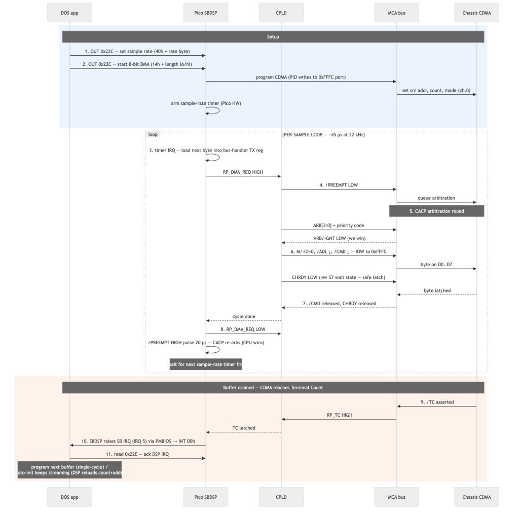
Step-by-step
- App configures sample rate. DOS app does
OUT 0x22C, 40h(set time-constant command) then a secondOUT 0x22Cwith the rate byte. Pico’s SBDSP emulator translates that to a hardware-timer frequency. - App starts DMA playback.
OUT 0x22C, 14h(DSP command 14h = 8-bit single-cycle DMA output) followed by two bytes for the buffer length (-1, low + high). The emulator does NOT touch CDMA directly here — it just records the playback parameters and arms its internal timer. The app is also responsible for having already programmed the chassis CDMA controller (viaOUTto ports 0x18-0x1F) with the source memory address + count + mode. - Per-sample timer fire. At each sample interval the SBDSP emu loads the next byte from its FIFO into the bus-handler’s TX register and raises
RP_DMA_REQto tell the CPLD “I want one bus cycle now.” - CPLD asks for the bus. Pulses
/PREEMPTLOW. Chassis sees the request and queues an arbitration round. - CACP runs arbitration. All competing masters drive their priority codes onto
ARB[3:0]in parallel; the chassis grants the bus to the highest-priority. Our card uses a low priority (CPU-friendly), but on an idle chassis we win quickly. - The IOW cycle. CPLD drives
M/-IO=0, pulls/ADLthen/CMDLOW, holds CHRDY LOW for a few extra ns (rev 57’s wait state) so the chassis CDMA controller has guaranteed data setup time, then watches CDMA latch the byte off D0..D7. - CPLD releases.
/CMDHIGH,/ADLHIGH, CHRDY HIGH, byte delivered. - Post-cycle cleanup. Firmware’s
iow_handler_donedropsRP_DMA_REQLOW (no more bytes pending right now) and pulses/PREEMPTHIGH for ~20 µs, forcing CACP to release us and re-arbitrate. The CPU usually wins the next round on an otherwise-idle chassis; we wait for the next timer fire. - Terminal count. When CDMA’s down-counter reaches zero, it asserts
/TCon the bus for one cycle. CPLD latches that intoRP_TCand the Pico’s SBDSP emulator knows the buffer is done. - DSP IRQ. SBDSP emulator raises the configured SB IRQ (typically IRQ 5 on SB / SB2 / SB Pro). The IRQ flows through PMBIOS’s PM_Int multiplexer to the chassis 8259, which dispatches
INT 0Dh(or whatever the SB IRQ vector maps to) to the DOS app’s registered ISR. - App ACKs + repeats. The app reads
0x22Eto clear the DSP’s IRQ flag, then either programs the next buffer (single-cycle mode) or leaves the DSP to keep streaming (auto-init mode where the DSP re-loads count/address itself).
The whole loop runs continuously for the duration of audio playback. At 22 kHz with a 4096-byte buffer, step 3 through step 8 fire 4096 times before step 9-11 fire once. At 44 kHz with the same buffer, it’s 4096 times in ~93 ms.
Each of those steps has a window where things can break:
- Step 4: CPLD output not actually reaching MCA edge (bodge wire fix)
- Step 5: priority code wrong or arbitration timing off
- Step 6: CHRDY not extending enough (Wolf3D gun shot regression)
- Step 7: CHRDY self-latching, holding bus past CACP deadline (POST 113)
- Step 8: pulse too short → CACP doesn’t re-arbitrate
- Step 9: /TC ignored → endless playback or missed buffer boundary
- Step 10: IRQ multiplexer drops the SB IRQ → app’s ISR never fires
- Step 11: app’s ACK not reaching DSP → DSP holds IRQ asserted, locks
up next cycle
Every one of those windows produced a unique class of debugging sessions, with its own LA capture and its own forehead-on-desk moment. Getting all 11 right at the same time is what “MCA audio works” actually means.
First TADA
June 3, 2026. The 8556 ran SBDIAG /A220 /I5 /D1. The autodetect passed. The Sound Blaster Diagnostic test played TADA. I had to play it three times to convince myself it was real audio and not a test pattern I’d memorized from the LA capture.
That same evening Wolf3D’s gun fired cleanly.
The chassis matrix turned green:
- 8550Z (286, 10 MHz): SBDIAG ✓, Wolf3D ✓
- 8555 (286, 16 MHz): ✓
- 8556 (286, 16 MHz): ✓
- 8557 (286, 16 MHz): ✓
- 8570 (386, 25 MHz): ✓ (after the unrelated MADE24 fix)
- P70 (gas-plasma 386): ✓
- 8580 (386): ✓
First sustained MCA audio on a Pico-based card. Probably 30 years
since IBM gave any thought to whether such a thing was possible.
Lessons
- MCA is not a more-complicated ISA. It’s a different bus architecture. CACP is not a more-complicated 8237. If you try to port ISA DMA thinking to MCA you’ll spend a week confused. Read the HITRA02 spec section on extended-DMA before writing a single line of CUPL.
- The CPLD source is not the silicon. Always verify with a logic analyzer that the decode matches what you wrote. The blk_220 bug would have eaten a week longer if I’d kept staring at
.pldsource instead of the LA. - WinCUPL has silent footguns. The OD-emulation pattern
PIN N = !X; X.OE = Xlooks right, compiles clean, and produces dead logic. The right pattern is two named signals. - You can’t have it all on a clock-by-clock basis. Rev 49–53 tried to keep
dreq_gatedperfectly clean by removing DMA terms fromio_match. That broke CHRDY on DMA writes, which corrupted audio. Rev 57 split into two decoders — one clean for SFDBK, one inclusive for CHRDY — and got both. Sometimes the right answer is two equations, not one cleverer one. - Patch wires are part of the design until proven otherwise. The
/PREEMPTbodge wire stayed in for six weeks before the WM11 board revision picked it up in copper. Patch wires aren’t ugly — they’re the fastest way to move forward when copper is wrong. - CACP timing budgets are forgiving for paced traffic, brutal for bursts. SBDSP at 22 kHz = one cycle per 45 µs, well below the per-grant deadline. A naïve “DMA as fast as possible” loop blows past it in microseconds. Pace your DMA to the audio rate; let CACP rest between cycles; the chassis is happy.
- POST 113 fires for “you didn’t release”, not “your cycle was
slow”. I spent days chasing nanoseconds inside the cycle handler before I realized the chassis was unhappy about a CHRDY self-latch that briefly re-asserted after the cycle’s natural end — extending the release window past the deadline. The cycle itself was fine. Don’t optimize what the symptom doesn’t actually blame. When you see POST 113, trace back from the chassis-side status bit (port 0x90 bit 5), not forward from the most recently-completed cycle. - First sound is a milestone worth celebrating even if it’s a square wave. The gap between “DMA is theoretically working” and “music plays” is bigger than you think; finishing it changes how you debug the rest.
- First-pass instrumentation lies. I had POST tracing on the serial UART from day one, and it told me POST 113 fired “after the last DMA cycle” — which I correctly read as “near the end of a cycle”. What it actually meant was “8-10 µs after the last cycle’s apparent end, because something didn’t release”. Until you wire the LA to the chassis-side status bit you’re guessing. The half-day spent on the instrumentation paid for itself many times over.
- Bus cycles aren’t independent — they share a state machine. The RP2350 bus handler keeps state across cycles (
RP_REL,HANDLED_IO, address-latch registers). If one cycle leaves that state half-set — because we silenced a signal it was waiting on, like CHRDY on DMA IOW — the next cycle inherits the contamination, and the wrongness shows up there instead of on the cycle that actually caused it. Wolf3D’s “disk read corruption” was really “the DMA IOW immediately before each disk MEMR left the handler in a bad state, so the disk MEMR read the wrong byte.” Always trace one cycle backward when debugging “this cycle is wrong” — the cause is often the one before.